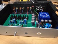
Well, I finally got this built. Worked first time and sounds fantastic though my old 6000HD Sennheiser headphones. Thank you Nelson and all the helpers on this thread!

First mod is away!

First impressions: definitely bassier and fuller, I like it
(Don't judge my amateurish soldering please)
First impressions: definitely bassier and fuller, I like it
(Don't judge my amateurish soldering please)
For C2 and C3 have in house silmic ii or cerafine. Will you mix them or use one type only? If mixing which goes in C2 and which in C3. Thanxs
C2 is for power supply decoupling/filtering.
C3 is in the signal path for DC blocking at the preamp output.
This information may help in choosing capacitors. 🤓
C3 is in the signal path for DC blocking at the preamp output.
This information may help in choosing capacitors. 🤓
Second mod away!
Replaced the input caps with 10uF film caps and did a 1u film bypass on the output caps.
Oh, I also switched to a Jameco linear power supply which I think improved things.
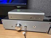
This is a major improvement, the sound is much smoother and clearer, the ACP is finally starting to give my Aune S17 Pro a run for its money.
Next I think I'm going to build a proper power supply for it...
Any technical downside using and external volume control before the acp+? I will install a jumper in-out instead of the 20k alps. Pot Ground i suppose remains without any connection? Highest output impedance of the passive pre before acp is 5k. Is r1 having issues seeing a jumper instead of the missing alps? Thanxs
Question: I notice that some amps (like the F5M for example) you're supposed to adjust the bias and offset values, but I don't see anything about that for the ACP (or the ACA for that matter). Is there a reason for that? Would be it be worth installing a trimmer into the ACP and playing with the values or is there nothing to be gained from it?
Both the ACA and ACA mini have adjustable bias. It's just the ACA+ (the headphone amp/preamp) that doesn't.
Though personally I just did what the build guide said to do on that.
Though personally I just did what the build guide said to do on that.
Strange enough I cannot find the psu testing procedure in the manual. Do I miss the correct guide? I have the 90% complete
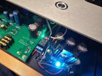
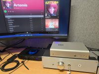
Finally finished after having the boards and components stored away for over 2 years! Sounds bloody marvellous!
Attachments
-
 20250307_185148.jpg723 KB · Views: 187
 -
 20250309_145816.jpg634.7 KB · Views: 192
 -
 20250309_145824.jpg850.5 KB · Views: 184
 -
 20250309_165620.jpg713.6 KB · Views: 198
 -
 20250309_184754.jpg603.6 KB · Views: 192
 -
 20250309_184802.jpg590.4 KB · Views: 196
 -
 20250309_194836.jpg570.6 KB · Views: 188
 -
 20250309_194924.jpg542.2 KB · Views: 175
 -
 20250309_200250.jpg645.7 KB · Views: 194
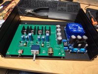
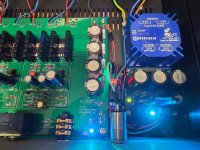
A few thoughts:
1. I see a ground wire connected to the stand-off/screw at the left side of the power supply board and to the safety ground at the IEC socket on the back panel. I am not familiar with the power supply board. Is the stand-off/screw connected to power supply ground? Or is the wire to connect the chassis bottom panel to safety ground? With an anodized chassis care should be taken to make sure all chassis panels behave as one electrically. That may require removing anodization at various spots to electrically connect all of the panels.
2. The power supply ground should be connected to safety ground, either directly or through a ground loop breaker, if it is not already connected.
2. I see what looks like an 0.47uf film capacitor connecting the ACP+ board Ground to the safety ground. What is the purpose of this capacitor? Is it for RFI control? If it is for RFI control, my understanding is that an 1nf ceramic, not film, capacitor is appropriate.
A few thoughts:
1. I see a ground wire connected to the stand-off/screw at the left side of the power supply board and to the safety ground at the IEC socket on the back panel. I am not familiar with the power supply board. Is the stand-off/screw connected to power supply ground? Or is the wire to connect the chassis bottom panel to safety ground? With an anodized chassis care should be taken to make sure all chassis panels behave as one electrically. That may require removing anodization at various spots to electrically connect all of the panels.
2. The power supply ground should be connected to safety ground, either directly or through a ground loop breaker, if it is not already connected.
2. I see what looks like an 0.47uf film capacitor connecting the ACP+ board Ground to the safety ground. What is the purpose of this capacitor? Is it for RFI control? If it is for RFI control, my understanding is that an 1nf ceramic, not film, capacitor is appropriate.
- Noise reduction: By bypassing high-frequency noise, the capacitor helps to create a cleaner and quieter audio signal.
- EMI mitigation: By routing high-frequency noise to earth, the capacitor can help prevent electromagnetic interference (EMI) from being radiated or conducted from the audio equipment.
- Safety: In some cases, a capacitor can help to isolate the audio ground from the earth ground, preventing potential safety hazards if a fault occurs.
Third mod away!

Someone earlier in this thread said they put big 3900 uF Panasonic caps in (https://www.mouser.com/ProductDetail/667-EEU-FC1V392) for the output caps. It's think they sound better but if there's a difference it's small and it's hard to tell exactly because I can't properly a/b.
The same poster also somehow put in these enormous input caps:

But I can't fit them on the board! Seems like they'd have to be stuck above the resistors which seems like a bad idea. An audio engineer friend of mine suggested I could glue them to the sides of the board and run wires from the leads, but that seems a bit much. I think I might just buy the axial versions instead and try those.
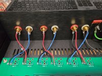
Oh, you can see above I also replaced the output RCA jacks with screw terminals (nice that the board provides extra holes that can be used for that). This is because I want to have two sets of outputs in my final build. For which I also just got the Galaxy case. Also the parts for the power supply came--I'm building an AMB Sigma11 for it. I'm going to put that into a separate chassis so that I can use it for other things if I want to. Will post more as I progress.
Someone earlier in this thread said they put big 3900 uF Panasonic caps in (https://www.mouser.com/ProductDetail/667-EEU-FC1V392) for the output caps. It's think they sound better but if there's a difference it's small and it's hard to tell exactly because I can't properly a/b.
The same poster also somehow put in these enormous input caps:
But I can't fit them on the board! Seems like they'd have to be stuck above the resistors which seems like a bad idea. An audio engineer friend of mine suggested I could glue them to the sides of the board and run wires from the leads, but that seems a bit much. I think I might just buy the axial versions instead and try those.
Oh, you can see above I also replaced the output RCA jacks with screw terminals (nice that the board provides extra holes that can be used for that). This is because I want to have two sets of outputs in my final build. For which I also just got the Galaxy case. Also the parts for the power supply came--I'm building an AMB Sigma11 for it. I'm going to put that into a separate chassis so that I can use it for other things if I want to. Will post more as I progress.
OMG I just realized I don't think the Panasonic caps will fit in the Galaxy case. Not sure what I'm going to do, supposed I could do the glue and wire thing or something. I could also cut holes in the top of the chassis as if for tubes which would be kind of absurd and hilarious. I'll have to figure something out.
EDIT: Decided I'll just return the 1U Galaxy chassis and get the 2U instead, which is only $5 more. Seems like the simplest solution (especially if the axial film caps also don't fit in the 1U chassis).
EDIT: Decided I'll just return the 1U Galaxy chassis and get the 2U instead, which is only $5 more. Seems like the simplest solution (especially if the axial film caps also don't fit in the 1U chassis).
Last edited:
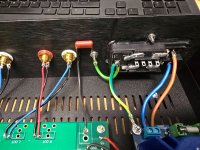
Fourth Mod:

These are the axial versions (more or less) of the big film capacitors I couldn't fit before. And even with these the legs wouldn't fit in the holes! So I had to take a bit of wire, solder it to the capacitor legs and then solder THOSE to the board. The result is a bit janky and there's clearly a cold joint somewhere on the left capacitor because if I push it a little the left channel goes out. Still there's a definite sonic improvement imo.
Still waiting for the larger chassis. Meanwhile, still building the power supply.
- Home
- Amplifiers
- Pass Labs
- Amp Camp Pre+Headphone Amp - ACP+