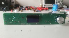
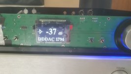
PSU in chassis is totally fine. Cutting IEC is a pain.
Good idea
Also good idea
Likely not necessary, certainly won’t hurt anything
I’d bridge it and just have the one switch
Any LED will work
Totally fine
ACP boards needs to be attached to ground. So does the pot. Yes, one metal standoff is a good plan. Also make sure all chassis panels are in electrical contact with another, this will require scraping paint/anodization.
Good idea, or you could just route the wires in that channel in general… it’s designed for that very thing.
I didn't know that, thanks! I was worried about the sharp-ish edges and mains wiring, but will investigate. I'll probably run the mains wires through some fibreglass tubing anyway for added protection and to make sure the zip ties don't cut the insulation.Good idea, or you could just route the wires in that channel in general… it’s designed for that very thing.
More generally, thanks for all of that. Glad to know I'm on the right track. If I can get a small pan brake for sheet metal I may still give the barrier thing a try just to see if I can - but it's handy to know it's not essential if it becomes a PITA.
Just wanted to ask the forum, I have an all-but-complete ACP+ ready to go - minus the LED.
Is it ok to power on and do the tests mentioned in the original article, and play music? (Until I purchase an LED)
Is it ok to power on and do the tests mentioned in the original article, and play music? (Until I purchase an LED)
Sorry for double posting, can't edit the previous post: after a couple false starts, the basic voltage checks passed and I have music! Headphones and line out into an ACA Mini both sound good.
Seeing a few earlier posts in this thread, I measured the voltage drop across R4's: 1.189V, and 1.158V for 125R (don't have the exact measured out of circuit resistances). Since this works out to 9.512mA and 9.264 mA, is it a problem that it is a little below in the 10mA specced in the design?
EDIT: the voltage drops were measured after only a few minutes of the preamp being on, I don't know if it takes a while for the preamp to reach a stable operating current/temperature (similar to ACA Mini)?
Last edited:
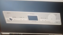
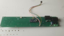
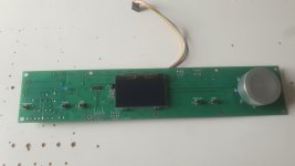
Being busy with the updated balanced ACP+ with all in one frontpanel control board for the preamp relais based volume control and OLED displayboard.
Also a Frontplate design which will be matching the PCB.
Hope that Modushop can produce it 🙂


Also a Frontplate design which will be matching the PCB.
Hope that Modushop can produce it 🙂
Attachments
Last edited:
Hello, I am looking for a next project to build and want to do a Class A headphone amplifier. At the moment I am using Beyer DT880 250Ohm, will probably upgrade later. Do you have a comparison/recommendation whether to go with the ACP+, AMB M³, Omicron, Dynalo or the Marsh Amp?
Hey folks,
So, I bought a strip of 100 J113s and a bench power supply (finally) and spent a pleasant day off testing and binning them for matching purposes while listening to King Gizzard Live at Red Rocks '22.
(thanks to all who have posted the relevant circuit diagram in this thread)
The spread of values was huge, from 15.5 to 25.5 mA, but 21.5mA seemed to be the mode. It took about 3 mins for each of them to settle, starting out very high before dropping to a relatively stable level. What I did notice was that idss readings were very sensitive to, and negatively correlated with, temperature. A slight cold breeze would send the reading up 0.3mA very quickly, before it working back down to the previous state.
I picked the highest value matched pair (24.5mA each) and reconfigured the circuit with a trimpot to find the needed resistance for 10mA. I had to use a 25 turn 1k trimpot as I didn't have a 200 ohm on hand, but with patience I found the selected pair achieved 10.00mA rock solid at around 99 ohms (actually 98.2 and 99.2 respectively). This makes me wonder how high the kit J113s are to need 125 ohms. 30mA?
Anyway, my question is related to temperature. My garage was a cool (but relatively consistent) 10C while all this testing was going on, which is likely significantly cooler than the inside of an ACP+ (I plan to put it in a chassis). Do I need to test again at a more sensible temp somehow, or am I going to be well within the ballpark as is? What's more important - hitting exactly 10mA, or a tight J113 match?
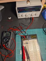

Nice PSU. Where did you buy it from?
That was from Core Electronics - for whatever reason they don't mention the brand in the listing, but it's GW Instek. 0-30VDC 0-3A x2.
My only criticisms are:
- it could do with a fine control, as it's only a fraction between .1V increments, it can be a bit twitchy
- the output button has a long throw before the click, so it's possible to think you've actuated it when you haven't if you're not looking or listening
But otherwise it works well. 12V measured 12.07V unloaded on my meter, which seems pretty fine to me.
Bit of cutting and drilling and dry fitting today. So far, so good. Cleared the IEC hole cutting hurdle. Hooray!
RCA sockets were just from the parts drawer - I'll make sure to have them match when it comes to it. I still seem to get things slightly skew-if here and there, but it's good enough work for the panels I won't be looking at. 😅
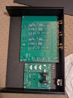
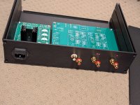
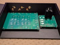
RCA sockets were just from the parts drawer - I'll make sure to have them match when it comes to it. I still seem to get things slightly skew-if here and there, but it's good enough work for the panels I won't be looking at. 😅


^ is that a linear psu for the acp!?
That's certainly the plan! I am not a fan of a billion power packs underfoot, so I thought this would be a good opportunity to practice doing an internal supply before stepping up to a power amp.
The board is an @rhthatcher FlexReg single rail board, which I was put on to after seeing something similar used in the Pearl 3 phono stage. Interestingly, it includes a position for a snubber resistor, although I need to do more reading to figure out whether I can get away with using a value found by another member for the AMGIS transformer I have, or whether I need to fork out for an oscilloscope and do the whole Quasimodo thing properly. I get the feeling I know the answer already, and real question is Rigol or Siglent.
I had also considered doing a Low Z High Z switch (32 & 300 ohm), but realised I'd either need a 4 pole switch and a breakout board (or 5 pole if I wanted a status LED for it), or a separate board with a couple of relays. At which point I decided that's something best left to future me who understands how to design PCBs. I have plenty of 35ish ohm headphones anyway.
Have a look at Quasimodo post #2540, @twofires . You can successfully optimize snubbers with a ~ 70 NZ$ "starter" oscilloscope.
Thanks Mark, I actually have that post in my open browser tabs at the moment. I'm still weighing it up, as I plan to get a proper scope eventually, so it might be time to do that.
I also have a Dayton DATS V3 USB thingo for speaker measurements that alleges it can function as an oscilloscope, though I'm not confident it is designed to work well outside audio signals. I don't yet know enough about scopes to determine what's sufficient.
While I'm picking everyone's brain, I've been looking at how to attach a large 4.7uf film resistor for C1, as appears to be the fashion for the tweakers among us.
Now, I'm not the best at figuring out what's electrically equivalent where PCBs are concerned, but it seems like inserting C1 into the inner through holes for R1 and R3 and then attaching the inner legs of those resistors to the cap legs point-to-point style might work fine?
Imagine the cap in this position, but lower and secured to the board with a stick on zip tie thing, then the resistors attached to the legs.
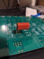

I would leave the resistors the way they are supposed to be inserted and solder the cap to the solder pads on the underside, securing it flat with some double sided tape.
Don't understand the reason why you want to halve the value of the cap though.
Doing that doubles the LF of the ACP.
Unless that cap is in addition to the 10uF as per the schematic.
In both cases the underside is the better place to make that addition.
Don't understand the reason why you want to halve the value of the cap though.
Doing that doubles the LF of the ACP.
Unless that cap is in addition to the 10uF as per the schematic.
In both cases the underside is the better place to make that addition.
Last edited:
I would leave the resistors the way they are supposed to be inserted and solder the cap to the solder pads on the underside, securing it flat with some double sided tape.
This is to the original C1 pads? I think it might actually just about fit that way to the top of the board, if the double sided tape is tall enough. I'll see what it looks like once everything else is in place. Cheers. 🙂
As for why, see post #2129 - in response to my asking @6L6 why he chose to do the same in post #2121.
One more question for now, back in post #595, @Mark Johnson you mentioned that ideal Q3 current was actually 2*(Vgs /1k) or similar. I just plugged my IRF610s into my DCA 75 Pro and it tells me Vgs (on) is ~3.6V a piece, which suggests about 7.2mA is the figure to hit. I'm I getting that right? That's a fair bit lower than the 10mA I was shooting for.
Last edited:
- Home
- Amplifiers
- Pass Labs
- Amp Camp Pre+Headphone Amp - ACP+
