@spiggs : find a way to share sixpack or two with other Greedy Boyz in neighborhood
You are right of course but after a few six packs everything sounds pretty good. More important though it makes for a very pleasant time.
Yes.
I was afraid you would say that.
Bridged sounds much better, in my opinion.It’s also more than double the power.
Apparently no one has strapped 2 of them to make a parallel bridged.

If one was to strap 4 of them into 2 sets of mono blocks, would all four amps need the same specification build? Or could you take two stock v1.6's and two modified ACA's to make the 2 mono blocks?
So I would connect each amp as bridged mono, use a RCA Y connector to each amps inputs, how are the speaker outputs wired? Would I need to jumper the two amps speaker negatives together and the amps positives to each speaker + & -?
What is the LED part number. I want to install orange or yellow color LED instead of red/blue.
Do you guys recommend any DIY dual mono power supply?
Try these Inolux HTOV511040UY
HTOV511040UY Inolux | Optoelectronics | DigiKey
I used them in my build with a 24k resistor, they are listed as yellow but have an orange color especially when run at low currents. The color is similar to orange neon but not quite. They are actually oval is shape but work just fine in the ACA.
Apparently no one has strapped 2 of them to make a parallel bridged.
or 4 of them in series/parallel. Is that even possible? Back in the day we used to gang up 4 Techron 7700 to get +/- 200V at 200A into horrible inductive loads - of course what was a different application.
Pretty much any LED will work. However some have attached resistors, but they will say if they do. The cheaper ones are usually less bright which is usually a good thing. We use various LEDs from various sources when we make the kits.
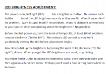
I decided to squander $2.00 of the builder's money. I installed a 25-turn trimmer potentiometer footprint on the PCB, in series with the LED, for project we're putting in the store soon. This trimpot lets the builder set and adjust the brightness to any desired level. They can also experiment: swap out different LEDs having different colors or different maximum viewing angles, and re-adjust the trimmer to get the desired brightness every time.
Your spouse thinks the LED is too bright? No problem, dial the trimmer. Etc.
Here is one way to spend a lot of money on a front panel LED
Having a pot without a series resistor is not a good idea for a DIY project. If the pot is at the zero resistance end, the LED will blow at power up. Many DIYers don't have the equipment to slowly turn on the project they are itching to try out. Nelson sometimes does this on Vbe multipliers. If the pot is at the zero resistance end, it's max fuse blowing bias.
Having a pot without a series resistor is not a good idea for a DIY project. If the pot is at the zero resistance end, the LED will blow at power up.
I combat this enemy, two different ways. First I use a trimpot with triangle pins footprint, ensuring it can't be installed backwards. This guarantees that rotating the trim knob clockwise increases the brightness, and rotating the pot counterclockwise decreases brightness, on every single unit, no matter who built it. The Builder's Guide .pdf document tells you how perform the adjustment (attachment #1 below).
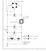
Second, I include resistor R7 in the schematic and on the PCB (attachment #2 below). This guarantees the LED current cannot exceed ((Vsupply-Vled)/820ohms) even if someone fails to follow the written procedure just mentioned. Observe how recklessly I have squandered the builder's money: a fixed resistor in series with a variable resistor! Sacre bleu. Also observe how I have exaggerated the "danger", to increase builders' motivation to turn down the brightness control before first power-up.
_
Attachments
Last edited:
I guess it'll be possible to modify my ACA with this, if it does avoid the "bump" at power on, that's great !
I guess it'll be possible to modify my ACA with this, if it does avoid the "bump" at power on, that's great !
I don't think this if for that? It's to turn down the LED brightness.
If you want to avoid the turn on "bump", you could consider using a cap multiplier. My ACA has no turn on sound at all, as the cap multiplier ramps up the power slowly, thus avoiding the bump or thump.
If you want to avoid the turn on "bump", you could consider using a cap multiplier. My ACA has no turn on sound at all, as the cap multiplier ramps up the power slowly, thus avoiding the bump or thump.
How to do that ? If you could elaborate a little , with pictures if possible, i'll be great.
Oddly enough, now that I've built my second aca to have 2 bridged monoblocks, there is absolutely no sound on power up or power down that I am able to notice. before they were bridged and when in standard stereo operating mode I would hear that very slight skweel like someone was trying to hold in a fart on power up, but thats gone compeletely in bridged mode.
when bridged , if there is a squeel , both halves are squeeling equally , so no difference to show on loudspeaker outputs
How to do that ? If you could elaborate a little , with pictures if possible, i'll be great.
Lots of info in this thread: Juma's Easy-Peasy Capacitance Multiplier
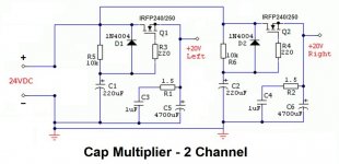
I've used two cap multipliers for my ACA - one for each channel. It has the added advantage of giving better channel separation when using one power supply. See diagram below.
This Cap Mx has about 4V drop, so start with 4V more than you need for the ACA. I'm using an enclosed Meanwell SMPS and I can set voltage higher than nominal. If you want 24V into the ACA, select a PSU that will give 28VDC.
The second picture shows the two Cap Mx's mounted on the bottom panel of my ACA. It gets hot, so you can also mount it on the heatsink.
Attachments

Last edited:
So, to convert my bridged monoblocks into parallel monoblocks....is thr easiest way to connect both negative speaker posts, then run the speaker output on the red and black speaker outs on the same side under the left RCA Jack input....would put the bridged switch in the town position.
- Home
- Amplifiers
- Pass Labs
- Amp Camp Amp - ACA