Another amp camp amp comes alive and sounds great!
I just have a question, it seems that one of the blocks gets hotter than the other one. They both share the same supply which gives out 19v / 5.27A, both built together piece by piece and have the a matching heat sink and tuned to 10v on drain.
I'd be happy if you have some pointers of what to look for. One is reasonably hot while the other one is significantly hotter, I can't put my finger on it (literally 🙂
Gideon
Because the voltage can be set, I think Q1 and Q4 are working correctly and that the problem is somewhere around Q2 or Q3.
The first thing to do would be compare resistance readings between channels with the power off. Use the Diode Check function on Q1 and Q2 between Source and Drain. If you find a short or low resistance, unsolder the part to see if the short is the part, or somewhere on the board.
Q3 regulates the current by sensing the voltage from the Drain of Q1 to the Source of Q2. That voltage should be close to 0.65 Volt. The 1K resistor R8 should have very little voltage across it. If the voltage is correct, R1, R2, R3 or R4 are too low in resistance or there is a short somewhere. You can compare voltages between the working and non-working channels.
If the voltage is too high, Q2 or Q3 is bad (assuming all connections are correct). Measure the voltage from Emitter to Collector of Q3 (or across C2). It should be about 5V. If it is close to zero volts, Q3 is doing it's job but Q2 is not functioning correctly. Replace Q2. If it is significantly over 5V, check Q3's voltage from Emitter to Base. If it is more than 0.7V, Q3 is not conducting. Replace Q3.
I ran across these "half brick" heat sinks (based on suggestion of Saturnus in the class D forum). They have rating of 4.7 deg C/W and are very economically priced ($3.65 ea ) as they are for standard DC to DC converters. Can this work for both mosfets or would one be required per mosfet?
VHS-95 CUI Inc | 102-1489-ND | DigiKey
VHS-95 CUI Inc | 102-1489-ND | DigiKey
An externally hosted image should be here but it was not working when we last tested it.
Even one per MOSFET really would be pushing it. I'd suggest looking for surplus sinks more like 3"x8"x1" for 2 MOSFETS
Last edited:
As posted previously but with a bit nicer front panel.
http://www.diyaudio.com/forums/pass-labs/215392-amp-camp-amp-aca-80.html#post3405346
http://www.diyaudio.com/forums/pass-labs/215392-amp-camp-amp-aca-80.html#post3405346
Any teaser pictures of the new ACA chassis?
Because the voltage can be set, I think Q1 and Q4 are working correctly and that the problem is somewhere around Q2 or Q3.
The first thing to do would be compare resistance readings between channels with the power off. Use the Diode Check function on Q1 and Q2 between Source and Drain. If you find a short or low resistance, unsolder the part to see if the short is the part, or somewhere on the board.
Q3 regulates the current by sensing the voltage from the Drain of Q1 to the Source of Q2. That voltage should be close to 0.65 Volt. The 1K resistor R8 should have very little voltage across it. If the voltage is correct, R1, R2, R3 or R4 are too low in resistance or there is a short somewhere. You can compare voltages between the working and non-working channels.
If the voltage is too high, Q2 or Q3 is bad (assuming all connections are correct). Measure the voltage from Emitter to Collector of Q3 (or across C2). It should be about 5V. If it is close to zero volts, Q3 is doing it's job but Q2 is not functioning correctly. Replace Q2. If it is significantly over 5V, check Q3's voltage from Emitter to Base. If it is more than 0.7V, Q3 is not conducting. Replace Q3.
Hi Loudthud,
I have checked all the things you mentioned:
Diode check between source and drain measures around 500 on both Q1 and Q2 in both sides the same (power disconnected).
D-Q1 to S-Q2, both measure around 0.62-0.63v on both sides
Across C2 is very close to 5v on both sides
Thanks for the help until now 🙂
Gideon
It looks like all the transistors are functioning correctly. The problem must be that one or more of R1, R2, R3, R4 are not the correct value, or current is flowing through C1 to the speaker.
The voltage from the Drain of Q1 to the plus side of C1 should be 0.366V and 0.253V from the plus side of C1 to the Source of Q2. A low voltage on one side points to which side has too low a resistance. If the sum of the voltages is not 0.62V, some current is flowing in C1 or somewhere else.
With no signal, the DC voltage at the speaker (-Out on the schematic) should be very close to zero volts. Verify that the polarity of the capacitor is correct. I made a mistake on one of my builds. I connected the +Out to +19V instead of ground. 😱
Note that it's a good idea to mount transistors low on the heatsink for best cooling efficiency. The top of a heat sink is usually several degrees warmer. I suggest about 1/3 the length from the bottom.
Even one per MOSFET really would be pushing it. I'd suggest looking for surplus sinks more like 3"x8"x1" for 2 MOSFETS
Each MOSFET dissipates about 10 watts right? The 4.7 deg C/W rating on this heat sink then means 47 deg C above ambient (20 deg C) or 67 deg C or 153 deg F. I guess that is a bit warm to touch but what is the temp that the MSOFET case needs to be kept below to work properly? It can probably handle a higher temperature?
what is the temp that the MSOFET case needs to be kept below to work properly?
The rule of thumb is: If you can light a cigar on it... it's too hot. 😛
It looks like all the transistors are functioning correctly. The problem must be that one or more of R1, R2, R3, R4 are not the correct value, or current is flowing through C1 to the speaker.
The voltage from the Drain of Q1 to the plus side of C1 should be 0.366V and 0.253V from the plus side of C1 to the Source of Q2. A low voltage on one side points to which side has too low a resistance. If the sum of the voltages is not 0.62V, some current is flowing in C1 or somewhere else.
With no signal, the DC voltage at the speaker (-Out on the schematic) should be very close to zero volts. Verify that the polarity of the capacitor is correct. I made a mistake on one of my builds. I connected the +Out to +19V instead of ground. 😱
Note that it's a good idea to mount transistors low on the heatsink for best cooling efficiency. The top of a heat sink is usually several degrees warmer. I suggest about 1/3 the length from the bottom.
Ok Some more findings and an action plan:
(please let me know if it's more appropriate to start a new thread around this, don't mean to hijack).
- Seems like its a faulty R3 or R4 on the hot block (Loudthud, you nailed it!! 🙂
The resistance across both of them sum up to be 0.9R where it should be around 1.36R (0.68x2) as it is on the good block.
Action plan is to just buy a new set of R1-R4 resistors and replace in both, probably not the white brick kinds 🙂
Measurements from what Loudthud suggested:
Running temperature:
On the hot block: C1+ to Q1 Drain = 0.348v / -0.254v
On the cooler block: C1+ to Q1 Darin = 0.366v / -0.22v
While warming up:
On the hot block: C1+ to Q1 Drain = 0.35v / -0.22v
On the cooler block: C1+ to Q1 Darin = 0.40v / -0.18v
With no signal:
On the hot block: -OUT = 0.01v
On the cooler block: -OUT = 0.09v
Thanks again, and I will report back with results.. until now the amp sounds amazing!
Gideon
Gideon,
These resistors are in parallel, meaning the total of their resistance is half the value of one (0.34 ohms). If you hand wired the board, perhaps you hooked them in series instead of in parallel.
These resistors are in parallel, meaning the total of their resistance is half the value of one (0.34 ohms). If you hand wired the board, perhaps you hooked them in series instead of in parallel.
Gideon,
These resistors are in parallel, meaning the total of their resistance is half the value of one (0.34 ohms). If you hand wired the board, perhaps you hooked them in series instead of in parallel.
🙂 you have a point there!
I guess I was jumping to quickly to conclusion after finding the first anomaly. I'll try to replace them and see if this solves the problem, hopefully I can do it today before I go to my friend and play the amp through his mysterious new speakers (fei-le full rangers).
Pass DIY Addict
Joined 2000
Paid Member
Amp Camp in our house
Some time ago, my daughter was working on her "circuits" unit in science class. She was telling me about the fun she and her friends had making light bulbs light up, etc with a small battery circuit. So, I got out my my Snap Circuits kit and we played around for the afternoon making all kinds of circuits. The one that she thought was the most fun was the radio that we built.
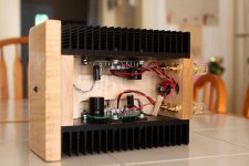
Seeing all of the fun she had building some circuits, I spent the next few weeks gathering all of the parts necessary for an Amp Camp Amp and and a small pair of speakers. I also spent a few days cutting and finishing a nice piece of hard maple for the chassis and drilling holes (I used the 2U sinks from the DIYAudio store) and routing holes in the speaker cabinets.
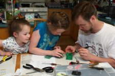
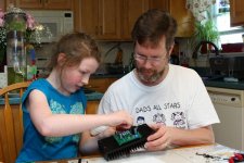
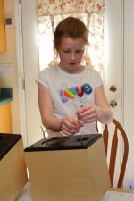
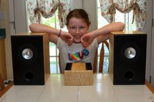
Fast forward a few weeks to her birthday. She was thrilled to unwrap a box full of little electronic parts and pieces. This past weekend, we spent the afternoon putting it all together. She bent all of the resistor legs, populated both boards, and helped me solder everything in place. After each part was in place, she clipped the legs off. We mounted the boards to the sinks and then attached the sinks to the wooden pieces for the chassis. We did a quick adjust to the pot (man, that is a REALLY sensitive adjustment) and then moved on to the speakers. I got her a pair of Mark Audio CHR-70 drivers (thanks to Planet10 for the suggestion!) and we put them in the Parts Express 0.25 cu ft cabinets. Finally, it was time for a listen. What a GREAT sounding little system for her iPod and MP3 player!
It's too bad we couldn't travel to California for Amp Camp to be with everyone, especially the master himself! But we brought a little bit of amp camp to our house for my daughter's birthday! Thank you, Nelson, for sharing another great design with all of us!
We had a great time working together and she has the satisfaction of knowing that she helped build her new stereo. It is the perfect size and power for her bedroom. I told her to be sure to keep an eye on it - I think it sounds so nice that I might just take it to work with me 😀
Pics are below.
Some time ago, my daughter was working on her "circuits" unit in science class. She was telling me about the fun she and her friends had making light bulbs light up, etc with a small battery circuit. So, I got out my my Snap Circuits kit and we played around for the afternoon making all kinds of circuits. The one that she thought was the most fun was the radio that we built.
Seeing all of the fun she had building some circuits, I spent the next few weeks gathering all of the parts necessary for an Amp Camp Amp and and a small pair of speakers. I also spent a few days cutting and finishing a nice piece of hard maple for the chassis and drilling holes (I used the 2U sinks from the DIYAudio store) and routing holes in the speaker cabinets.
Fast forward a few weeks to her birthday. She was thrilled to unwrap a box full of little electronic parts and pieces. This past weekend, we spent the afternoon putting it all together. She bent all of the resistor legs, populated both boards, and helped me solder everything in place. After each part was in place, she clipped the legs off. We mounted the boards to the sinks and then attached the sinks to the wooden pieces for the chassis. We did a quick adjust to the pot (man, that is a REALLY sensitive adjustment) and then moved on to the speakers. I got her a pair of Mark Audio CHR-70 drivers (thanks to Planet10 for the suggestion!) and we put them in the Parts Express 0.25 cu ft cabinets. Finally, it was time for a listen. What a GREAT sounding little system for her iPod and MP3 player!
It's too bad we couldn't travel to California for Amp Camp to be with everyone, especially the master himself! But we brought a little bit of amp camp to our house for my daughter's birthday! Thank you, Nelson, for sharing another great design with all of us!
We had a great time working together and she has the satisfaction of knowing that she helped build her new stereo. It is the perfect size and power for her bedroom. I told her to be sure to keep an eye on it - I think it sounds so nice that I might just take it to work with me 😀
Pics are below.
Attachments


kiss for both little builders/helpers
I also have one and I must admit ( proudly ) - she's smarter than I am
Looks like you have what you need, but I bet they would get a kick out of doing some Foam Core Cornu horns - Just for fun.
Great Story!!
Great Story!!
Pass DIY Addict
Joined 2000
Paid Member
Thanks for the kind comments, guys! We really had a great time working on it. It's kinda interesting that my daughter's first stereo features a Class-A amplifier designed by Nelson Pass.
Cool speaker design, Bob!
Cool speaker design, Bob!
- Home
- Amplifiers
- Pass Labs
- Amp Camp Amp - ACA