Hello, while waiting for the kits, i'm assembling a dual mono chassis using hifi2000 heatsinks and hifi2000 galaxy front/back plates.
I'm crating a "mini dissipante" case for the camp amp.
If someone is intrested i can post some images tomorrow morning.
I'm crating a "mini dissipante" case for the camp amp.
If someone is intrested i can post some images tomorrow morning.
would love to see what you have in mind kikko... I am looking at something similar to slomatt's mini-aleph chassis - similar size heatsinks.
Last edited:

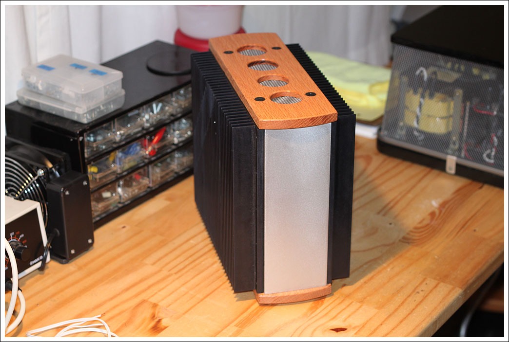
As promised i'm posting some images of my heatsinked case.
Ok actually the case is composed by parts and mask tape... but the project is quite simple:
Panel: _____
Heatsink: HHH
______
H H
H H
H H
______
The heatsinks will be drilled and the holes tapped.
Last part will be creating an upper and a lower panel:
Panels are from modushop (like everything else in this little project..) and needs to be cutted to fit (a simple jigsaw is ok).
Here you can see the heatsinked case near another case (for the pre).
I will post more info soon: now i have to drill a couple of heatsinks 🙂
An externally hosted image should be here but it was not working when we last tested it.
Ok actually the case is composed by parts and mask tape... but the project is quite simple:
An externally hosted image should be here but it was not working when we last tested it.
Panel: _____
Heatsink: HHH
______
H H
H H
H H
______
The heatsinks will be drilled and the holes tapped.
Last part will be creating an upper and a lower panel:
An externally hosted image should be here but it was not working when we last tested it.
Panels are from modushop (like everything else in this little project..) and needs to be cutted to fit (a simple jigsaw is ok).
An externally hosted image should be here but it was not working when we last tested it.
Here you can see the heatsinked case near another case (for the pre).
I will post more info soon: now i have to drill a couple of heatsinks 🙂
Some images in my previous post aren't showing..
No problem, i have almost completed the case:
Drilling heatsinks
Now i need to fix the front and back panels to the heatsinks.
Thank you for watching 🙂
No problem, i have almost completed the case:
An externally hosted image should be here but it was not working when we last tested it.
Drilling heatsinks
An externally hosted image should be here but it was not working when we last tested it.
An externally hosted image should be here but it was not working when we last tested it.
An externally hosted image should be here but it was not working when we last tested it.
An externally hosted image should be here but it was not working when we last tested it.
Now i need to fix the front and back panels to the heatsinks.
Thank you for watching 🙂
damping factor sim
I though it might be quite a tease to simulate the circuit and measure the output resistance on the simulation. Disclaimer these simulations are mostly accurate but sometimes like a republican campaign speeche it can differ from reality by a vast margin. The actual measurement by Mr. Pass and or others on the actual amp supersedes these simulations. I am using a method described by Rod Elliott of Australia on his Elliott Sound Products - The Audio Pages web site where the output voltage is measured across a known load and with no load attached. Then the following formula is applied:
Vu=Voltage out un-loaded
VL= Voltage out loaded
RL=Load resistance
Zo = Output impedance
Zo = (Vu - VL) / (VL / RL)
I am assuming most people are building the amp camp to drive full range drivers or at least high efficiency drivers. The multi-way speaker crowd usually want an output impedance as low as possible (zero point something proceeded by several zeros). For full range drivers we want a little higher output impedance something more like a 300B amp which I have seen quoted with damping factors between 2 and 6. Converted to output impedance it is between 4 and 1.3 ohms. I personally use an 8ohm power resistor on my class-d amp to make it sound more decent on my Fostex 6” drivers. My observation is that the value is not super critical as long as it's a few ohm, though I don't have the power resistors to try values higher then ten ohms.
OK, lets get to it:
The value is it is drawn by Mr. Pass is:
Feedback NetWork 10K/68.1K
Vin = 0.5v @ 1KHz
Vout@8ohm load = 2.49509V
Vout@1Kohm load = 2.88103V
Zo = (Vu - VL) / (VL / RL)
1.2374385 = (2.88103 - 2.49509)/(2.49509 / 8)
6.4649677 damping factor = 8/1.2374385
The value given by Mr. Pass is a damping factor of 3 which would be 2.66 ohms. The value I simulate is off by 1.4ohms not that much, but I don't think I could hear the difference between one ohm more or less. If we assume the simulation works perfectly the difference can be explained by the model picking slightly different transconductances for there parts compared to the lot of parts used in the true build (just speculation).
Attachments
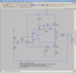
Figure 3 on page 2 of the A40 article shows the incremental output impedance for different classes of amps. Is there any way to measure this on an exsisting amp? Could you measure it by using small signals and adjusting the DC level to different points? Would the output capacitor interfere with operating conditions (ie no load current flowing) at different DC points?
Link: http://www.passdiy.com/pdf/a40.pdf
Link: http://www.passdiy.com/pdf/a40.pdf
Take an Output Voltage and Output Current measurement at 2 (widely spaced) points. Subtract the 2 Voltagte and the 2 Current measurements. Divide the Voltage difference by the Current difference and thats the Output Z under those conditions.
Sorry I don’t have the simulator in front of me at the moment (I am at work). I should have stated that I made the rail voltage 18.5v instead of 19.5v because I have a laptop power supply which is 18.5v@6.5A (that should drive a pair of these).
Those two resistors are substituting for the trim pot, I adjusted the ratios up and down until I see no clipping (top or bottom) with an input sine wave of 1.5v. I think it’s about half the supply voltage. But I can confirm in my next post.
The true value here will depend on the gate to source threshold voltages of the input and bottom fet, those will be different for every device, you grab from the bag. That’s why a trim pot is needed there. If the amp goes into clipping this measurement method will not work, so I made sure to stay out of that range. I retested with two input voltage ranges (0.5 and 1.0v), and the variation in Zout was small, just to double check myself.
I am trying (simulating) other topologies which are very similar to this. Well it seems like we have some time before we get the kits. I am working with models of power Jfets. I found 4 different input stage topologies that will drive the same Amp camp power stage without needing a negative supply. They are differential p-jfets (like J2), p-fet with source feedback (like JLH), n-jfet with source feedback (using folded cascode to flip polarity (like 1/2 of original x amp patent)) and, normal amp camp with shunt voltage reference added to jfet source. When I find time I’ll draw them up and present my findings here if anyone is interested. Sorry I’m a bit of an armchair engineer .
.
Those two resistors are substituting for the trim pot, I adjusted the ratios up and down until I see no clipping (top or bottom) with an input sine wave of 1.5v. I think it’s about half the supply voltage. But I can confirm in my next post.
The true value here will depend on the gate to source threshold voltages of the input and bottom fet, those will be different for every device, you grab from the bag. That’s why a trim pot is needed there. If the amp goes into clipping this measurement method will not work, so I made sure to stay out of that range. I retested with two input voltage ranges (0.5 and 1.0v), and the variation in Zout was small, just to double check myself.
I am trying (simulating) other topologies which are very similar to this. Well it seems like we have some time before we get the kits. I am working with models of power Jfets. I found 4 different input stage topologies that will drive the same Amp camp power stage without needing a negative supply. They are differential p-jfets (like J2), p-fet with source feedback (like JLH), n-jfet with source feedback (using folded cascode to flip polarity (like 1/2 of original x amp patent)) and, normal amp camp with shunt voltage reference added to jfet source. When I find time I’ll draw them up and present my findings here if anyone is interested. Sorry I’m a bit of an armchair engineer
.Take an Output Voltage and Output Current measurement at 2 (widely spaced) points. Subtract the 2 Voltagte and the 2 Current measurements. Divide the Voltage difference by the Current difference and thats the Output Z under those conditions.
That gives you one number essentially at the center of the output swing. Also, when you change the output amplitude, you get a different number.
I want a plot as the output swings from rail to rail. Does the negative impedance current source or the single ended nature of the amp cause asymmetry?
You can do these measurements at many points. the more points, the higher the accuracy vs range. You can do several points across the range and try to draw a strait line through them to see if it is even worth doing so many points.
Here is a plot of distortion with and without feedback into 8 ohms. I just connected the generator with output impedance set to 50 ohms to the junction of R11 and R12 for the open loop plot. The X-Y plot is the input vs output of the open loop amp. With the loop connected, the plot looks like a straight line. You can see the gain is changing (slope of the line) therefore, the output impedance must be changing. This makes sense because the gain of Q1 goes up as the current increases when Q1 pulls the output low.
Attachments
I can’t help thinking I am a little bit like one of those people that go running around mindlessly taking all of Nelsons schematics and cascoding all active devices and insisting it will sound better without even having compared. So let me first say I have not built this yet and I am not sure if it will improve or degrade or leave the sound unchanged.
I have tried simulations of Amp Camps with power jfets, more specifically the power Jfet, the SJEP120R100A which can be picked up from Newark | US - Electronic Components Distributor | Electronic Parts Distributor for $28.04. There is a similar (really the same) part without the -A- on the back of the part number, the -A- just denotes that it is for audio. I think they pick the ones out that are not the best suited for ultra-high frequency on-off switching. The only difference in the data-sheet is that the audio grade has 2ohms more on their gate, which means nothing for us, we put 100ohm gate stoppers on it anyway. Though the few bucks they reduce the cost by when compared to the non-A version is appreciated.
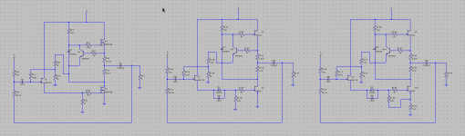
Now it is an enhancement-mode Jfet but you cannot just plug it in because the gate of the power Jfet is between 0.75v-1.25v. And the input Jfet (LSK170 or 2SK170) has a gate-source cut-off voltage of (-0.2 - -1.5v). So that's not going to work well, even if you happen to hand pick parts that just get between the two points, as soon as you start running AC signals through the 1k bias resistor the current will get pinched off. The output wave form on the simulator was just not a pretty picture (at least in the simulation, don’t know about real life).
There are several workarounds, the simplest way I have thought of is to add a voltage source under the input Jfet and reduce the 1k resistor at the gate of q1 to 250 ohm. This will keep about the same bias current through the LSK170 jfet. This can be seen in fig2 in the abstract PDF (you can zoom in infinitely with PDF’s, if the symbols look familiar it is because I hacked the f3 pdf schematic to draw these) and in the middle simulation screenshot attached. At first my expectation was that the jfet would have to work too hard driving the 250 ohm load with its source. However I was surprised, it turns out that the jfet does not have to swing 4X more current, only about 1.5X more (dam don’t have the simulation in front of me to confirm again). I don’t understand why that is, maybe the higher gain (transconductance ). The 250 ohm value will keep about the same ~4mA (it was actually 6mA in simulation) bias current through the jfet. The voltage source can be made from any one of a number of parts (resistor, zenner diode, precision shunt voltage reference, led, string of bais to collector tied transistor, … ) and can be bypassed with a cap to lower the noise. The value should be in the ball park of 2.5v-6v ideally shooting for 4v.
The output imp. has unfortunately come down to well under an ohm (in simulation). This may be because it has more gain thus more feedback, thus more correction. It can be brought back up again (getting back to the suspected –good- value where the output imp is about the same as a 300B amp) by using a source resistor on the bottom power jfet. As long as we are doing this the 250 ohm resistor can be attached to it. This makes the little jfet work less hard because the voltage at the power source resistor rises and falls with signal, so the amount of current the little jfet has to supply is less. Though this cannot be done so easily by hacking the original board, and at any rate it needs to be actually built and evaluated to see how it sounds in real life.
Distortion:
The distortion from all these amps is not sufficiently large to cause the waveform to be so altered as to make the change visible by eye. It still looks like a sine wave. If I look at the point where the input and feedback are summed the power jfet amp with source resistors looks a lot cleaner then the mosfet version.
One reason at least I am sure the Amp camp did not start out using these JFets is because the cost of 4 of them is still over $100.00USD.
I have tried simulations of Amp Camps with power jfets, more specifically the power Jfet, the SJEP120R100A which can be picked up from Newark | US - Electronic Components Distributor | Electronic Parts Distributor for $28.04. There is a similar (really the same) part without the -A- on the back of the part number, the -A- just denotes that it is for audio. I think they pick the ones out that are not the best suited for ultra-high frequency on-off switching. The only difference in the data-sheet is that the audio grade has 2ohms more on their gate, which means nothing for us, we put 100ohm gate stoppers on it anyway. Though the few bucks they reduce the cost by when compared to the non-A version is appreciated.
Now it is an enhancement-mode Jfet but you cannot just plug it in because the gate of the power Jfet is between 0.75v-1.25v. And the input Jfet (LSK170 or 2SK170) has a gate-source cut-off voltage of (-0.2 - -1.5v). So that's not going to work well, even if you happen to hand pick parts that just get between the two points, as soon as you start running AC signals through the 1k bias resistor the current will get pinched off. The output wave form on the simulator was just not a pretty picture (at least in the simulation, don’t know about real life).
There are several workarounds, the simplest way I have thought of is to add a voltage source under the input Jfet and reduce the 1k resistor at the gate of q1 to 250 ohm. This will keep about the same bias current through the LSK170 jfet. This can be seen in fig2 in the abstract PDF (you can zoom in infinitely with PDF’s, if the symbols look familiar it is because I hacked the f3 pdf schematic to draw these) and in the middle simulation screenshot attached. At first my expectation was that the jfet would have to work too hard driving the 250 ohm load with its source. However I was surprised, it turns out that the jfet does not have to swing 4X more current, only about 1.5X more (dam don’t have the simulation in front of me to confirm again). I don’t understand why that is, maybe the higher gain (transconductance ). The 250 ohm value will keep about the same ~4mA (it was actually 6mA in simulation) bias current through the jfet. The voltage source can be made from any one of a number of parts (resistor, zenner diode, precision shunt voltage reference, led, string of bais to collector tied transistor, … ) and can be bypassed with a cap to lower the noise. The value should be in the ball park of 2.5v-6v ideally shooting for 4v.
The output imp. has unfortunately come down to well under an ohm (in simulation). This may be because it has more gain thus more feedback, thus more correction. It can be brought back up again (getting back to the suspected –good- value where the output imp is about the same as a 300B amp) by using a source resistor on the bottom power jfet. As long as we are doing this the 250 ohm resistor can be attached to it. This makes the little jfet work less hard because the voltage at the power source resistor rises and falls with signal, so the amount of current the little jfet has to supply is less. Though this cannot be done so easily by hacking the original board, and at any rate it needs to be actually built and evaluated to see how it sounds in real life.
Distortion:
The distortion from all these amps is not sufficiently large to cause the waveform to be so altered as to make the change visible by eye. It still looks like a sine wave. If I look at the point where the input and feedback are summed the power jfet amp with source resistors looks a lot cleaner then the mosfet version.
One reason at least I am sure the Amp camp did not start out using these JFets is because the cost of 4 of them is still over $100.00USD.
Attachments
just a blatant advertising - you can have those for less than from Newark - from Tea-Bag ..... matched
I don't think that is a criticism. I think he means HE (ZM) is advertising Tea-Bags devices.. Although you never know! 😉
The amp camp amp seems to be inspiring all sorts of creative thought and analysis.
Awesome!
Well... back to ordering..
Mark
The amp camp amp seems to be inspiring all sorts of creative thought and analysis.
Awesome!
Well... back to ordering..
Mark

Sorry I would have added it had I known from web searches I assumed they were the only supplier. Here is the link:
http://www.diyaudio.com/forums/grou...sfet-group-semisouth-r100-jfet-group-buy.html
Any ballpark idea on what the kit will cost and what will\will not be included?
http://www.diyaudio.com/forums/grou...sfet-group-semisouth-r100-jfet-group-buy.html
Any ballpark idea on what the kit will cost and what will\will not be included?
- Home
- Amplifiers
- Pass Labs
- Amp Camp Amp - ACA