Hi, yes me too.
Only for my interest what kind of problem did you have with your VFL 22k and how did you fix it?
Only for my interest what kind of problem did you have with your VFL 22k and how did you fix it?
Yes. It was a nightmare finding a suitable replacement.
I honestly can't remember everything I've done. I repaired this amp slowly over time.
Things I think u should do.
1. The legs on the 4452's are very close together. Make sure u don't have any solder bridges there.
2. Make sure u move the jumper on the ps driver card to 9v setting. Though I had to give it like 9.7v to fire up properly. Also it won't always start the output section if u r using too low of current. I used around 20 amps.
Mine blew catastrophically because the owner wasn't using any fuses. Yes u read that correctly, a 22k watt amplifier being abused without any fusing because he thought they were a "bottle neck" in the power path. Anyway mine probably failed very differently than yours
Hello everyone, even today I spent 3 hours in the company of my VFL 20K in a vain attempt to repair it. On the driver board I found a degraded through pad referring to the TL072 so I replaced it. I turned on the amp, after a few seconds the IR2184 oscillates only on pin4 (LO Side). No sign of life on pin7 (HO Side).
In this condition I do some measurements. Without input signal, the LM311 generates a square wave that my Hantek reads at 50Hz(?) but as the input freq varies, the LM311 varies its oscillation and takes it to pin1 of the IR2184. LO Side output follows the same frequency. No output on pi 7 (HO Side).
I have mounted only 6 pairs of output Mosfets. The amplifier tries to start, but when the oscillation starts on the Low side gate, it goes into protection and switches off the smps. Red LED on.
I took the IR2184 off the driver board and turned the amp back on. No protection, the amplifier remains operational. Green LED on.
I looked at everything.... what am I still missing??? I was also thought of a possible malfunction of the protection circuit that processes the output signal through a resistor that connects the mother board to the PWM controller. If I try to isolate the protection circuit and turn on the amp, how much damage do you think I can do??
I trust you and your experience
Did you supply voltage to the high-side driver when you were looking for signal before you installed the output FETs?
The high-side can't produce drive (outputs out of circuit) unless you supply voltage to the high side. I typically use a 9v battery.
I agree with you.
What I don't understand is why during the start-up phase of the amp, the power circuit of the TC and the HO side of the driver starts supplying 12v then after a few seconds (about 10/12) it starts going down to 0v. On the output I read a peak of almost 90v dc and everything goes into protection. Has it ever happened to you?
What I don't understand is why during the start-up phase of the amp, the power circuit of the TC and the HO side of the driver starts supplying 12v then after a few seconds (about 10/12) it starts going down to 0v. On the output I read a peak of almost 90v dc and everything goes into protection. Has it ever happened to you?

Yes you are right, the reference is not directly to GND but on the midpoint of the Mos+ and Mos- through a low value resistance. Okay.
let's leave the probes alone, what could be the cause that sends the amp into protection? why does the amp stay operational with the driver off the board?
let's leave the probes alone, what could be the cause that sends the amp into protection? why does the amp stay operational with the driver off the board?
Did you confirm that the oscillation of the 2184 didn't start until after rail voltage had fully developed?
Disabling the protection circuit is an option but it's risky, especially using full rail voltage.
Are the outputs in it, the new outputs or just what remained after it failed?
Do you have a split power supply that you can use for a lower rail voltage? It would need to be about ±20v.
Are the outputs in it, the new outputs or just what remained after it failed?
Do you have a split power supply that you can use for a lower rail voltage? It would need to be about ±20v.
They are still the original mosfets that I disassembled and checked one by one after the amp failed. I found 7 of them exploded due to condensation build-up. The remaining ones are all working and with the same Rds ON.
I have an external dual rail power supply... tell me what to do. Thanks Perry.
I have an external dual rail power supply... tell me what to do. Thanks Perry.
You will remove the rectifiers and connect your supply to the output terminals.
Confirm that the amp can produce no rail voltage to the rail caps and that the rail caps are fully discharged before connecting your supply.
Are there output FETs (at least 1) in every bank of the output section?
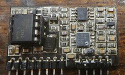
Post a photo of the PS driver board that's used in this amp. I think I know what it is but I'm not sure.
Confirm that the amp can produce no rail voltage to the rail caps and that the rail caps are fully discharged before connecting your supply.
Are there output FETs (at least 1) in every bank of the output section?
Post a photo of the PS driver board that's used in this amp. I think I know what it is but I'm not sure.
- Home
- General Interest
- Car Audio
- AmericanBass VFL competition 20k in protect mode