
@gioan_77
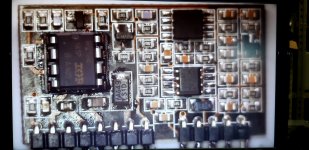
The break on the control board between the 10k resistor and the ceramic capacitor is a factory break. They were broken on several driverboards and worked perfectly.
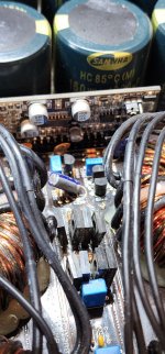
How many Amperes of power supply are available for start-up? When starting, due to the empty buffers, a high current is required to build up the rail voltage in a short time, because the delay of the ir2184 is quite short.
The break on the control board between the 10k resistor and the ceramic capacitor is a factory break. They were broken on several driverboards and worked perfectly.
How many Amperes of power supply are available for start-up? When starting, due to the empty buffers, a high current is required to build up the rail voltage in a short time, because the delay of the ir2184 is quite short.
The interruption on the control board between the 10k resistor and the ceramic capacitor does not affect the operation... I noticed it when I got the schematic through reverse engineering. I limited my power supply to 10V and 5.6A because I don't want to do too much damage.The break on the control board between the 10k resistor and the ceramic capacitor is a factory break. They were broken on several driverboards and worked perfectly.
How many Amperes of power supply are available for start-up? When starting, due to the empty buffers, a high current is required to build up the rail voltage in a short time, because the delay of the ir2184 is quite short.
Does moving the jumper to the other position let the amp power up?
I agree. Current limiting could be causing the amp to go into protection.
I agree. Current limiting could be causing the amp to go into protection.
Unfortunately, this is not the case. when amplifier build up full rail voltage the capacitors stored charge can blow up all output mosfets etc.I limited my power supply to 10V and 5.6A because I don't want to do too much damage.
The only solution is a reduced input voltage, e.g. 11V instead of the normal 14-16V. 5-6A input current is very little, build the rail voltage too slowly.
I don't know I've never tried..... in mnhipop101's post it just says to check this location. The current absorption is decidedly high in the start-up phase, after a few seconds the current stabilizes at around 3 amps, the relay group activates and when the driver oscillation should start, the amp goes into protection. This doesn't happen when the mosfets or the IR2184 driver are off boardDoes moving the jumper to the other position let the amp power up?
I agree. Current limiting could be causing the amp to go into protection.
so you suggest me to increase the current ratio and leave a lower voltage... I'll try this too, thanks.Unfortunately, this is not the case. when amplifier build up full rail voltage the capacitors stored charge can blow up all output mosfets etc.
The only solution is a reduced input voltage, e.g. 11V instead of the normal 14-16V. 5-6A input current is very little, build the rail voltage too slowly
At this point any suggestions are welcome
Do you have a split power supply that you can use for a lower rail voltage? It would need to be about ±20v.
Perry, we started this yesterday...explain to me what you mean I have to checkYou will remove the rectifiers and connect your supply to the output terminals.
I didn't make suggestions on the voltage and current. Using current and voltage limiting of a power supply can vary in the way they operate. That's why I used current limiting resistors or no limiter on a 25 amp 13.5v supply.
Did anything change when the jumper was moved to the other position?
Did anything change when the jumper was moved to the other position?
I thought you wanted me to take some measurements using an external power supply so as not to run into the protection circuit.... I didn't move the jumper because now I'm at home (it's night in Italy now) and I was about to go to bed 😉
I'll try tomorrow and I'll tell you what happens when I move the jumper (although I don't think this is the solution to my problem)
I'll try tomorrow and I'll tell you what happens when I move the jumper (although I don't think this is the solution to my problem)
Mine would go into protect before the relays kicked in when I didn't have enough current. If there are any measurements I can take that may help u out let me know. Our amps are identical circuits

I don't know your name but thank you very much. Let's keep in touch because I will surely ask you for some specific measurements. Thanks again. My name is Andrew.Mine would go into protect before the relays kicked in when I didn't have enough current. If there are any measurements I can take that may help u out let me know. Our amps are identical circuits
Hi
You can power the output board with out the power supply. I do this for some full bridge amps and well as these big half bridge amps. There is a guy on you tube with some really good information on amp repairs.
Here is the link to hi channel: https://www.youtube.com/@ellensburgamplifier/videos
I know he did do a video not so long ago where he shows you how to power up just the audio board with very low voltage thus making it safer to work on the sound stage.
Hope this info helps
- Home
- General Interest
- Car Audio
- AmericanBass VFL competition 20k in protect mode