Acko,
am I right in thinking that the MCK u.FL connection in the S03 digital inputs is sort of performing 2 functions?
So it is the input for MCK which travels through the 4 channel Isolator, gets reclocked by RCK and ends up as an output, but also it's connected to the EXT CLK > Amanero CLK which goes through the 2 channel isolator?
What I'm wondering is because the DDDAC doesn't use the MCK output from the S03, whether it's possible to split the 2 functions at this S03 MCK input so I can still output the EXT CLK signal to my BBB, but also I can input, isolate and reclock an additional data signal? (this way I could have dedicated right left mono signals which the Botic driver can apparently output)
I know it's not possible without cutting and bodging the board a little, but am I understanding it correctly or missing something there?
I won't have the board infront of me for a day or so to trace the tracks and confirm that MCK is connected to both isolators and is therefore input and output at the same time.
thanks,
James
James,
You can repurpose the MCKout channel - just cut the track to pin#3 of U9 and then attach wires directly to pin#3 and gnd connection from pin#2 of U9. This becomes an additional data channel for your mono version of DDDAC
Just I do it.
I can't understand what wrong I do!
It plays at half speed of normal.
a) I set the MCLK/1 but I see that the default amanero set is MCLK/2
b) I removed the R3 (R22) complete from the S03 board and jumper this position. Nothing! The same behavior, plays at half speed.
The 1KHz test is demonstrated as 500Hz test.
Any suggestion?
See if you can select MCLK/1 and do a "write flash". If not maybe this prescaler is now hardcoded! Will check with Amanero.
Jumper R3? will not help, the same effectI removed the R3 (R22) complete from the S03 board and jumper this position
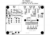
If you are bypassing the divider for your build then remove R3 and then connect end of R2 to end of R4 pad as in pic
Attachments
Last edited:
Excellent, thank you 🙂James,
You can repurpose the MCKout channel - just cut the track to pin#3 of U9 and then attach wires directly to pin#3 and gnd connection from pin#2 of U9. This becomes an additional data channel for your mono version of DDDAC
See if you can select MCLK/1 and do a "write flash". If not maybe this prescaler is now hardcoded! Will check with Amanero.
Jumper R3? will not help, the same effect
If you are bypassing the divider for your build then remove R3 and then connect end of R2 to end of R4 pad as in pic
Select the mclk/1 and do a "write flash" = No success (the flashing was done succesfully).
Bypass the divider = Yes a success achieved and it works well untill 192KHz (also works well the clock frequencies). Frequencies bigger than 192KHz don't play well.
Select the mclk/1 and do a "write flash" = No success (the flashing was done succesfully).
Bypass the divider = Yes a success achieved and it works well untill 192KHz (also works well the clock frequencies). Frequencies bigger than 192KHz don't play well.
Thanks, all reported to Amanero. Hope this gets fixed soon.
I now have a handy usb microscope which makes the job of seeing teeny things MUCH easier 🙂 so I'll have another go at mounting these tiny NDK clock chips to the adapter boards soon.
I'd like to test them before fitting them to the s03, but I don't understand how the Stand-By connection works and what output to expect. Could anyone explain please?
I understand if I supply 3.3v and gnd then I should see roughly 1.6v from the clock output, but what do I need to do with the Stand-By pad and what should I expect from the clock output? I see from the data sheet it has 3 available states, but it doesn't say what they are and how to achieve them 😕
thanks,
James
Just for interest, here's a pic of the screen from the USB microscope @ 100x

The print is a little hard to see as I've scratched it a little with my tweezers. The ruler lines are 1/2mm.
I've put some permanent marker on the pin1 corner which I can see with my eyes now.
From what I've read, if I ground the standby pin, I should expect the clock output to stop. So I'll mount both oscillators to their adapter boards and give them a test.
Not long now till synchronous clocking from bbb to dddac....
Just for interest, here's a pic of the screen from the USB microscope @ 100x
An externally hosted image should be here but it was not working when we last tested it.
The print is a little hard to see as I've scratched it a little with my tweezers. The ruler lines are 1/2mm.
I've put some permanent marker on the pin1 corner which I can see with my eyes now.
From what I've read, if I ground the standby pin, I should expect the clock output to stop. So I'll mount both oscillators to their adapter boards and give them a test.
Not long now till synchronous clocking from bbb to dddac....
James, you are going alright with the preparations. Standby pin to gnd will stop the oscillators and output will be HiZ. Standby pin open or Vcc(3.3V) will enable the outputs
Cool, Thanks.James, you are going alright with the preparations. Standby pin to gnd will stop the oscillators and output will be HiZ. Standby pin open or Vcc(3.3V) will enable the outputs
No joy with that tonight. I don't get a clock output from the 1 chip I've mounted, so I'm going to wait until my solder paste arrives and re-do them both.
If that doesn't work, I'll just get some nice easy big oscillators instead
Hi James,
Very nice build
Looking at you pictures I decide eventually to give a chance to the BBB and in the weekend I will build the S03.
It is long time now that the board is in the drawer and have all the parts including the 2 Crystek clocks 45.x and 49.x. Acko suggest me already to use the NDK 22 family but I don't have them and as first trial I will use the Crystek.
What is not clear to me is the "software" part and actually is the reason why I didn't build yet the S03.
My previous experience with the rPi was very hard and without the HUGE help from palmito I will never succeeds to have it working... THANKS palmito 🙂
About the BBB I understand that I have to flash the miero firmware and I found it already. That is the easy part but what about the setting? I see in the miero blog that I have to set the parameters but I don't know how.
I can just suppose that I have to connect to the BBB through Putty and follow the instructions from the miero blog but I am not sure at all.
I am sorry for the silly question but I am not a "linux" guy 😱
Hi Enrico, Editing the conf files using Vi or other can be a bit tricky. I've used a windows program called WinSCP. It a long time favorite of mine. It's much more userfriendly then trying to navigate through the filesstructure in Putty and it has a good text editor. It also makes it easy to drag and drop files to and from your local drive to the BBB.
WinSCP :: Free SFTP and FTP client for Windows
WinSCP :: Free SFTP and FTP client for Windows
Hi Enrico, Editing the conf files using Vi or other can be a bit tricky. I've used a windows program called WinSCP. It a long time favorite of mine. It's much more userfriendly then trying to navigate through the filesstructure in Putty and it has a good text editor. It also makes it easy to drag and drop files to and from your local drive to the BBB.
WinSCP :: Free SFTP and FTP client for Windows
Many thanks stijn001 for the link. I will give a look and let you know.
Cheers,
Enrico
Enrico,
You are not alone. I will be needing help myself when the SuperCape comes up for tests. Perhaps something like a crib sheet for setup will help a lot! - so do not have to worry too much about Linux stuff 😀
You are not alone. I will be needing help myself when the SuperCape comes up for tests. Perhaps something like a crib sheet for setup will help a lot! - so do not have to worry too much about Linux stuff 😀
Enrico and Acko,
I'm happy to help you guys with this if you need. It's not so bad really and like Stijn says, there's a few ways of making it easier 🙂
I'm happy to help you guys with this if you need. It's not so bad really and like Stijn says, there's a few ways of making it easier 🙂
Hi Acko,
Let me know if I can also assist with Linux. Picking up the skills the date I started to appreciate Miero's driver for BBB. Currently have linux JRiver 20.0.66(as file management/navigation) streaming to BBB via Ethernet cable.
Cheers,
Chanh
Let me know if I can also assist with Linux. Picking up the skills the date I started to appreciate Miero's driver for BBB. Currently have linux JRiver 20.0.66(as file management/navigation) streaming to BBB via Ethernet cable.
Cheers,
Chanh
Enrico and Acko,
I'm happy to help you guys with this if you need. It's not so bad really and like Stijn says, there's a few ways of making it easier 🙂
Thanks James... your help will be really appreciate 🙂
I now have a handy usb microscope which makes the job of seeing teeny things MUCH easier - James
James - would you make a recommendation? Been thinking about buying one for a while. TIA - Pat
- Home
- Group Buys
- Amanero Isolator/Reclocker GB