Acko, thanks for this clarification.
I have confused a lot when reading this message (thread: M2TECH Hiface USB->SPDIF 24/192Khz asynch)".
The MCLK table at this 9023 datasheet says, that for 45+/49MHz clocks (TurboMasterClock Output on S03) the appropriate FS are:
44,1 = 1024*44,1= 45,1584MHz
48 = 1024*48 = 49,1528 MHz
88.2 = 512*88.2 = 45,1584MHz
96 = 512*96 = 49,1528 MHz
176.4= 256*176,4 = 45,1584MHz
192 = 256*192 = 49,1528 MHz
352.8= 128*352,8 = 45,1584MHz
384 = 128*384 = 49,1528 MHz
------------------------------------------------
Red=not compatible FS (it marks with "-")
Bold=optimum FS
Underline=non optimum FS
The MCLK table at this 9023 datasheet says, that for 22+/24+MHz clocks (MasterClock Output on S03) the appropriate FS are:
44,1 = 512*44,1 = 22,5792MHz
48 = 512*48 = 24,576 MHz
88.2 = 256*88.2 = 22,5792MHz
96 = 256 * 96 = 24,576 MHz
176.4=128*176,4 = 22,5792MHz
192 = 128*192 = 24,576 MHz
352.8 =64*352,8 = 22,5792MHz
384 = 64*384 = 24,576MHz
------------------------------------------------------
Red=not compatible FS (it marks with "-")
Bold=optimum FS
Underline=non optimum FS
Add later
What clock combination is the better for 9023, finally?
Last edited:
Getting a little tricky to cover the entire range!
Are you able to play 44.1k at all on 9023 with 45/49M clocks?
Are you able to play 44.1k at all on 9023 with 45/49M clocks?
Yes, at this time with 45+/49+ clocks the 44.1/48 files play well (turbo master clock output).
Do you mean that this setup is preferable?
Do you mean that this setup is preferable?
Yes, at this time with 45+/49+ clocks the 44.1/48 files play well (turbo master clock output).
Do you mean that this setup is preferable?
The MCLK table at this 9023 datasheet says, that for 45+/49MHz clocks (TurboMasterClock Output on S03) the appropriate FS are:
44,1 = 1024*44,1= 45,1584MHz
....
Indicates not supported but works...
How does this then compare with 22/24Mhz from MCK output of S03?
Last edited:
Yes, indicates not supported to 64 or 1024, but works both of them.
I have the impression that the turbo master output plays a little better. Something like better separation of instruments at the space and the background is more silence.
I have the impression that the turbo master output plays a little better. Something like better separation of instruments at the space and the background is more silence.
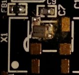
It's major PITA to solder but you got it right.Sorry for stupid question, but can anyone confirm if I got the orientation of the NDK clock correct? Thought I had it figured out, then not so sure😕
Yes, indicates not supported to 64 or 1024, but works both of them.
I have the impression that the turbo master output plays a little better. Something like better separation of instruments at the space and the background is more silence.
...concurs with that from others also, the higher clock rate giving better resolution and SQ so long as low phase noise clocks are used. As long as this high rate does not break the DAC chip just use it with 49/45Mhz clocks 🙂
almost done
I have done the smt parts. Used paste and toaster oven. Came out pretty good for a first effort. Too much paste resulted in a couple of solder bridges that I have to fix. Clock PS has a bridge and a short to sort out. Overall I have continuity in all the right places.
So, did you finished soldering s03?
I have done the smt parts. Used paste and toaster oven. Came out pretty good for a first effort. Too much paste resulted in a couple of solder bridges that I have to fix. Clock PS has a bridge and a short to sort out. Overall I have continuity in all the right places.
Attachments
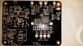
Turned out prety decent. Photo is not extremely detailed but I would double check pins on U1 ref. voltage. Also did you decide which capacitor for C4?
Turned out prety decent. Photo is not extremely detailed but I would double check pins on U1 ref. voltage. Also did you decide which capacitor for C4?
Agreed. Had a bridge. May still be shorted. For c4 I have the smt cap. If all works plan to put a 4.7u BG N ND a small one right on the pin as experiment. If it seems I have messed up ps too much my backup is to use a 3 pin rev by Ian Canada in place. It is optimized for clack and should be ok.
Acko, as I told you in the past, I work on a Sampling Rate Indicator Project.
I think that the following amanero pins aren't nessecery to joined on S03: F3, F2, F1, F0, D64, DSDOE, aren't they?
I think that the following amanero pins aren't nessecery to joined on S03: F3, F2, F1, F0, D64, DSDOE, aren't they?
Better late than never
Finally all done.. solder bridges removed and cleaned up. Looks great, and tests fine on the bench.
Questions:
1. I will only be using 50mhz clocks. Has anyone cut the trace between R3 and R13? Is the cut point at the line by U5?
2. I will first use it with stock PS. Has anyone tried external regs at J2 and J4? I have some nice low noise regs by Ian Canada that I am thinking of trying here.
Walter
Attachments
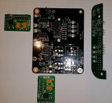
Hi Wlowes, I did cut the trace right at the white line next to where it says U5. I didn't try J2/J4.., but should be fine, that's what they are there for.
Some debugging to do
I know I am late to this party, but hope the many that have paved the way can help guide me.
My set up is BBB with acko cape (simple not dsd) then S03 then Ian I2S to PCM to a Ryanj tda1541a board.
Previously worked well with BBB to WaveIO to Ian I2S-PCM to RyanJ brd.
So the change is removed the WaveIO and inserted cape and s03. Also went from Volumio to ieero.com distro.
So far I have os up/mount to NAS working/BBB happily playing music at 44.1. But no sound.
When I built the S03, I tested 3.3v to all 3 consumers ok. 1.7v on each of the clock outputs. When I connected it to Ian I2S/PCM, it shows power and mclk leds but the I2S led not lighting.
I figure that since the BBB is happy playing @44.1, then it is clearly getting mclk. I am thinking I might have a connection problem with ufl connectors on the s03 or even on the input to Ian I2s/PCM board. I thought they all tested ok for continuity and no shorts, but could have missed a weak solder joint. They are devilish hard to solder with an iron.
I am so far just using botic distro with all defaults so could be things I need to set there, but I am thinking the Ian PCM board should see good I2S even if BBB is not working.
Any other thoughts? Wish I had a scope!
Last edited:
- Home
- Group Buys
- Amanero Isolator/Reclocker GB