Member
Joined 2009
Paid Member
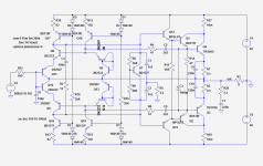
Here you are:can you post the .asc file for us to play with ?
Attachments
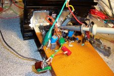
I have begun some tests on a real prototype.
There are some discrepancies compared with the sim, essentially stability/compensation issues, but the first results look promising.
Most of the transistor types are different though, which could be an explanation.
By somewhat increasing the compensation caps, I can get a clean squarewave.
Linearity assessment will be a difficult task and will require some creativity. It could be some time before I can report results on that aspect.
Attachments
Hi Elvee,
Have you made a listening test with prototype? How does it sound compared to your other designs? I wonder if you catch something extraordinary within those complexity.
Regards.
Have you made a listening test with prototype? How does it sound compared to your other designs? I wonder if you catch something extraordinary within those complexity.
Regards.
Yes, I had that curiosityHi Elvee,
Have you made a listening test with prototype?
Desperately neutral and unremarkable, but people with golden ears should take up this task.How does it sound compared to your other designs?
guitar/line buffer proposition
Hi
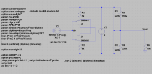
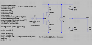
this time I have the idea of small signal pp source follower buffer with floating power supply.
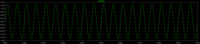
the results are for 1Vpp at the input, the load is 10k.
for guitar the loads are much higher, 220k-10Meg which means lower distortion.
the circuit is easy for mounting inside the guitar together with the battery.
remember about hf blocking circuits.
Hi
this time I have the idea of small signal pp source follower buffer with floating power supply.
the results are for 1Vpp at the input, the load is 10k.
for guitar the loads are much higher, 220k-10Meg which means lower distortion.
the circuit is easy for mounting inside the guitar together with the battery.
remember about hf blocking circuits.
Attachments

Last edited:
Very nice padamieckei!!!!
Ultra simple and elegant
The difference between a Porche and a Lamborghini - both good, but totally different.
However, what is the connection between performance and JFET matching?
Thanks for sharing!
🙂
Ultra simple and elegant
The difference between a Porche and a Lamborghini - both good, but totally different.
However, what is the connection between performance and JFET matching?
Thanks for sharing!
🙂
The main quality of this circuit is its wire-like behavior;unfortunately, it is also its main deficiency....
The main quality of this circuit is its wire-like behavior;unfortunately, it is also its main deficiency....
🙄
it still has caps, so it has a potential to tweak by the audiophiles😉😀
???
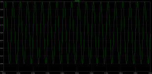
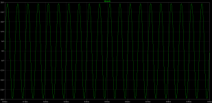
something is wrong with this circuit and ltspice probably fooled us.
look at the output when input signal is 40V pp with 10k load and 9VDC power supply...😕🙄😱 😀
😀
The main quality of this circuit is its wire-like behavior;unfortunately, it is also its main deficiency....
something is wrong with this circuit and ltspice probably fooled us.
look at the output when input signal is 40V pp with 10k load and 9VDC power supply...😕🙄😱
😀Attachments
 yes, but after connecting it works even better...
Hi
this time I have the idea of small signal pp source follower buffer with floating power supply.
the results are for 1Vpp at the input, the load is 10k.
for guitar the loads are much higher, 220k-10Meg which means lower distortion.
the circuit is easy for mounting inside the guitar together with the battery.
remember about hf blocking circuits.
Very 😎🙂
Thx-RNMarsh
cannotbe
to be clear:
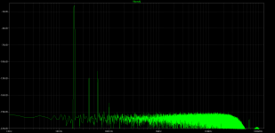
this probably cannot be true: it works without drains connection, anybody could explain?:
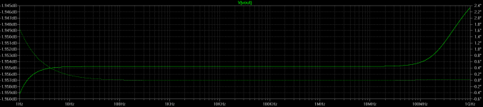
Harmonic Frequency Fourier Normalized Phase Normalized
Number [Hz] Component Component [degree] Phase [deg]
1 2.000e+04 1.597e+00 1.000e+00 0.00° 0.00°
2 4.000e+04 5.066e-07 3.172e-07 89.96° 89.96°
3 6.000e+04 1.912e-06 1.197e-06 -0.01° -0.01°
4 8.000e+04 6.322e-10 3.959e-10 -70.72° -70.72°
5 1.000e+05 2.499e-09 1.565e-09 175.66° 175.66°
6 1.200e+05 7.395e-10 4.631e-10 79.83° 79.83°
7 1.400e+05 5.937e-10 3.718e-10 -60.34° -60.34°
8 1.600e+05 2.264e-10 1.418e-10 109.61° 109.61°
9 1.800e+05 7.347e-10 4.601e-10 -126.81° -126.81°
Total Harmonic Distortion: 0.000124%
to be clear:
this probably cannot be true: it works without drains connection, anybody could explain?:
Harmonic Frequency Fourier Normalized Phase Normalized
Number [Hz] Component Component [degree] Phase [deg]
1 2.000e+04 1.597e+00 1.000e+00 0.00° 0.00°
2 4.000e+04 5.066e-07 3.172e-07 89.96° 89.96°
3 6.000e+04 1.912e-06 1.197e-06 -0.01° -0.01°
4 8.000e+04 6.322e-10 3.959e-10 -70.72° -70.72°
5 1.000e+05 2.499e-09 1.565e-09 175.66° 175.66°
6 1.200e+05 7.395e-10 4.631e-10 79.83° 79.83°
7 1.400e+05 5.937e-10 3.718e-10 -60.34° -60.34°
8 1.600e+05 2.264e-10 1.418e-10 109.61° 109.61°
9 1.800e+05 7.347e-10 4.601e-10 -126.81° -126.81°
Total Harmonic Distortion: 0.000124%
Attachments
I could not understand this either when I discovered the drains were not connected in the first place! New science! Congratulations to you!
Quite simple:to be clear:
this probably cannot be true: it works without drains connection, anybody could explain?:
When I said that, I actually meant it: there is no way power can be taken from the DC source and be transferred to the load.The main quality of this circuit is its wire-like behavior;unfortunately, it is also its main deficiency....
This means that all of the load current is supplied by the input source: in short, it buffers nothing, and the role of the DC supply is to forward-bias the gate junctions of the FETs.
I thought it was immediately apparent, but it seems it wasn't after all....
Quite simple:
When I said that, I actually meant it: there is no way power can be taken from the DC source and be transferred to the load.
This means that all of the load current is supplied by the input source: in short, it buffers nothing, and the role of the DC supply is to forward-bias the gate junctions of the FETs.
I thought it was immediately apparent, but it seems it wasn't after all....
Elvee
you are great

- Status
- Not open for further replies.
- Home
- Amplifiers
- Solid State
- Alternative buffer topologies