Well I think I may have finally found some parts to tackle a tube amp project.
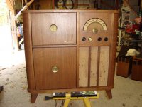
The donor is a 50's? Rogers-Majestic console. I can't find specific info on it.
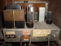
It has the following tubes.
7Q7 Pentagrid
7A7 Vacuum Pentode RF/IF-Stage
7B6 Double Diode-Triode Audio
6v6GT beam power tetrode
5Y3GT Full Wave Power Rectifier
So I'm thinking I need the last 3. I also have a 6AU6 and a 6J5 if needed.
I guess it will be more of a scavenge then a conversion, that's fine.
I know I have hours of research ahead of me, but any input/advice/links are appreciated.
The donor is a 50's? Rogers-Majestic console. I can't find specific info on it.
It has the following tubes.
7Q7 Pentagrid
7A7 Vacuum Pentode RF/IF-Stage
7B6 Double Diode-Triode Audio
6v6GT beam power tetrode
5Y3GT Full Wave Power Rectifier
So I'm thinking I need the last 3. I also have a 6AU6 and a 6J5 if needed.
I guess it will be more of a scavenge then a conversion, that's fine.
I know I have hours of research ahead of me, but any input/advice/links are appreciated.
Attachments

Now were talking. If you noticed in the multi way forum I posted speakers and such that I got from a flea market.
Any how check this out, it's got :
12AX7
12AT7
6AV6
2 x 6V6GT
5Y3GT Rect.- I also have one of these in the other amp.
I am think I might have something doable here.
I wonder would this thread be better in the TUBE/VALVE section???
Feel free to move it.
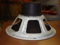
It also came with a nice vintage Jensen alnico speaker. I think this may sound nice with a guitar as most woofers do. I don't know if you would call it a driver or woofer? It had a basscoil in front of it for LPF, but in reality could just be a driver. I'm confused. lol
Any how check this out, it's got :
12AX7
12AT7
6AV6
2 x 6V6GT
5Y3GT Rect.- I also have one of these in the other amp.
I am think I might have something doable here.
I wonder would this thread be better in the TUBE/VALVE section???
Feel free to move it.
It also came with a nice vintage Jensen alnico speaker. I think this may sound nice with a guitar as most woofers do. I don't know if you would call it a driver or woofer? It had a basscoil in front of it for LPF, but in reality could just be a driver. I'm confused. lol
Attachments
Last edited:
Nice wood
I think you are thinking about making a guitar amp??? People use the word "amp" to mean different things, on craigslist electonics list the only kind of amp is the kind that uses 12 VDC and drives 1 ohm speakers at an insane and unlistenable watt levels. When I make an amp, it is for recorded music, or maybe my organ or apple macintosh driven keyboard.
Actually, I like your donor cabinet. A new turntable in the top, some freshening up of the electrolytic caps and the speaker rubber, you'd have a nice monophonic hi-fi to match the collection of mono organ records I was just donated. (Nobody wanted them, not even the charity resale shop). Or, you could hide a speaker in the bottom and a tweeter in the lid and go for new fangled "stereo".
My current system, that I am playing a lot of organ and high church music on this week, looks like I need to install a neon "BEER" sign (chose your brand, it's mortons up there isn't it?) and a wire mesh grill to keep the beer bottles off the faces of the musicians.
Last edited:
Thanks for the link Stalker, it will come in handy. I am checking a few videos on youtube with that amp.
I wouldn't mind a little more gain, although I beleive the fender users 12AT7s, so I guess I could mod it a bit.
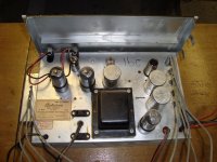
I spent a couple hours tonight removing most of the things I won't need, 12v lighting pigtails, feedback loop, tone stack, etc.
I wouldn't mind a little more gain, although I beleive the fender users 12AT7s, so I guess I could mod it a bit.
I spent a couple hours tonight removing most of the things I won't need, 12v lighting pigtails, feedback loop, tone stack, etc.
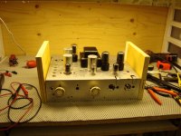
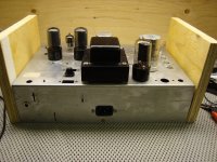
Ok making some progress I suppose.
First I wired up a 3 prong power cord, 2.5A SloBlo fuse and a regular power switch.
I also installed the speaker and input jacks.
I removed the tone controls and lights etc, trying not to disturb too much.
When I first got the amp I plugged it in, it hummed. However I should have plugged in an audio source first to see if it actually works.
I wired up some gain stages, with no luck. I plug in my guitar and it just faintly hums a bit like before. Oh boy.
The preamp is loosely based on Mesa/soldano. I also used the layout posted by stalker above as a bit of a guideline.
I was hoping to make some progress on my own with out asking for too much help, but now I'm stumped.😱
I understand its probably a bad cap(s) maybe a tube. Probably my wiring as well.
I was hoping to at least get some noise. Wah. I don't mind spending the money on some new caps etc, I'm just not sure on values yet. I do however have more old parts I could use.
Any tips or tests would be appreciated. In the meantime I'll keep on reading. I can post better/zoomed in pics of anything.
Attachments
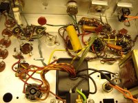
electrolytic caps
Test on electrolytic caps. Date inscribed is yyww where yy is last two digits of year and ww is week 1 -53. 2010-19yy>20 is a bad cap or likely to go bad if it ever warms up. Tall can caps for tubes come from FP factory, sold in US by triodeelectronics.com or tubesandmore.com. Or you can put 4 axial caps on two phenolic headers under the chassis, often cheaper. tubeandmore has the phenolic headers, also glass reinforced boards with lots of turrets on 2"x1/2" spacing favored by guitar amp builders. Both have 600v solid core hookup wire, lacking the ROPS certification for sale in europe. Once you get the cap to a non-explosive state (old electrolytics sometimes explode when the water boils) turn on side, clip negative of 600V scale to chassis, touch with one hand plus of meter to output tube grid. Speaker should make big pop. Hope you have read tube safety for newbies at top of tube amp thread. Tube repair website www.geofex.com/ampdbug/ampdebug.htm is often useful. Best of luck in the future.
Test on electrolytic caps. Date inscribed is yyww where yy is last two digits of year and ww is week 1 -53. 2010-19yy>20 is a bad cap or likely to go bad if it ever warms up. Tall can caps for tubes come from FP factory, sold in US by triodeelectronics.com or tubesandmore.com. Or you can put 4 axial caps on two phenolic headers under the chassis, often cheaper. tubeandmore has the phenolic headers, also glass reinforced boards with lots of turrets on 2"x1/2" spacing favored by guitar amp builders. Both have 600v solid core hookup wire, lacking the ROPS certification for sale in europe. Once you get the cap to a non-explosive state (old electrolytics sometimes explode when the water boils) turn on side, clip negative of 600V scale to chassis, touch with one hand plus of meter to output tube grid. Speaker should make big pop. Hope you have read tube safety for newbies at top of tube amp thread. Tube repair website www.geofex.com/ampdbug/ampdebug.htm is often useful. Best of luck in the future.
Last edited:
Yes I have been following safety rules.
I'm going to try that trick tonight when I get home. Thanks! Every little bit would help me to narrow it down.
Is there a safe way to hook the DMM up to the preamp stages to veryify signal going through that, ie voltage swing when I play the strings?
I'm going to try that trick tonight when I get home. Thanks! Every little bit would help me to narrow it down.
Is there a safe way to hook the DMM up to the preamp stages to veryify signal going through that, ie voltage swing when I play the strings?
Dmm's
my Sears $29 dmm is useless at frequencies other than 50-60 hz, the lowest AC scale it has is 200V which is also pretty useless for audio. I proved it with a scope later, the meter misses stuff in the audio frequencies (8vpp) it should see. I bought a 20 mhz scope off craigslist for $40, and a scope probe for $50 (B&K scope, scope probes from mouser.com) If you can't find a used scope, find a used low wattage output transformer like from a bogen PA amp or something- I picked up one at Salvation Army resale for $15. wire inputs of transformer from capacitor off plate (600v .1 capacitor) to ground, secondary of transformer to a little speaker. Again, turret board or phenolic header is usefull to wire this up safely. Ensure wire to cap rated 600v. In a pinch, wire the transformer from this chassis to the preamp tube output caps, instead of the output tube output cap. You should hear something.
my Sears $29 dmm is useless at frequencies other than 50-60 hz, the lowest AC scale it has is 200V which is also pretty useless for audio. I proved it with a scope later, the meter misses stuff in the audio frequencies (8vpp) it should see. I bought a 20 mhz scope off craigslist for $40, and a scope probe for $50 (B&K scope, scope probes from mouser.com) If you can't find a used scope, find a used low wattage output transformer like from a bogen PA amp or something- I picked up one at Salvation Army resale for $15. wire inputs of transformer from capacitor off plate (600v .1 capacitor) to ground, secondary of transformer to a little speaker. Again, turret board or phenolic header is usefull to wire this up safely. Ensure wire to cap rated 600v. In a pinch, wire the transformer from this chassis to the preamp tube output caps, instead of the output tube output cap. You should hear something.
my Sears $29 dmm is useless at frequencies other than 50-60 hz, the lowest AC scale it has is 200V which is also pretty useless for audio. I proved it with a scope later, the meter misses stuff in the audio frequencies (8vpp) it should see.
Almost all multi-meters are only designed to read 50/60Hz, they are useless for audio - either a scope, or an AC miliivoltmeter, should be used.
Ok so I performed the first test. When I applied the probe t the 6v6 grids I did get an audible crackle, through my 2x12 cabinet.
As soon as I sat down I noticed an area where I think the problem is. It's at a 47 cap before it enters the 12AU7. I need to get this sorted. My understanding is this tube takes the signal and distributes it to the PP tubes.
I am still going to do the preamp test. If/when I get it working, I'll ebay some caps and replace them all. I understand there will be some risk untill then.
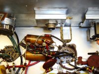
Here is the area in question. It's the lower of the 2 yellowish bar-shaped caps. The signal comes in from the 1m pot, then goes nowhere. It's the last terminal on the right.
As soon as I sat down I noticed an area where I think the problem is. It's at a 47 cap before it enters the 12AU7. I need to get this sorted. My understanding is this tube takes the signal and distributes it to the PP tubes.
I am still going to do the preamp test. If/when I get it working, I'll ebay some caps and replace them all. I understand there will be some risk untill then.
Here is the area in question. It's the lower of the 2 yellowish bar-shaped caps. The signal comes in from the 1m pot, then goes nowhere. It's the last terminal on the right.
Attachments
I soldered the terminal to number #2 on the 12au7.
Pretty fackin nifty if you ask me, this definatly has potential.
I think I have too much gain, I think it's really compressing the sound alot. The gain pot is almost usless. I need to add a grid resistor or 2, or another pot in between gain stages.
Any tips on losing some of the compression/bumble bee sound with out losing too much of the sizzle?
When the sound fades away it kinda crackles away, rather then gradually getting quiet. I have to sort out if this is from too much gain, or just a bad cap(s).
I can start to make a parts list tonight, now that I have a functioning amp. 🙂
Thanks for all your help IndianaJoe. This is fackin awesome.
This is a DIY nut I have been wanting to crack for years.
Glad your happy. I have no idea what the yellow cap is, but the brown one appears to be unsealed wound paper-foil. I would replace every one of those, and every electrolytic cap, before I replaced the first tube that didn't show white getter (the silver stuff) or cracked glass. Unsealed paper foil caps drift in value over the years due to water action on the paper, and oxygen attack on the paper, too. Use 600V plastic dielectric, I'm using vishay spragues with polyprophylene. Ebay caps are often out of date electrolytics. Life is too short, buy 2000 hour up rated electrolytics and don't do it again for 20 years. I'm redoing electrolytics (quality ones) that I installed in 1974, I tend to stay with my hobby projects. The bargain electrolytics I picked up in 1982 dated 1974, are going in the trash, not the amp. The vendors listed above have "sales" on electrolytics when they get 2 years old. Also Newark.com, if it doesn't have a * sale tag on it, it is less than 2 years old. After you get the caps to proper value, there is a lot of guitar amp tweaking over at music-electronics-forum.com. I'm not welcome over there because I'm an effete piano-organ-synth player who modifies hifis to play LP's better. Rattling the windows with Joan Jett on the hifi doesn't count on MEF.com, you have to strum the strings yourself.
Crackle- On my transistor ST120 amp, it had a faint frying pan crackle over the years that was annoying. When I replaced the 5uf input tantalum capacitors (installed 1982 the last time I repaired it, but caps were found on the "bargain" table) with ceramic aerovox 10 uf 50V CPO dielectric ones this spring (a big no-no according to JCurl), the crackle went away.
Crackle- On my transistor ST120 amp, it had a faint frying pan crackle over the years that was annoying. When I replaced the 5uf input tantalum capacitors (installed 1982 the last time I repaired it, but caps were found on the "bargain" table) with ceramic aerovox 10 uf 50V CPO dielectric ones this spring (a big no-no according to JCurl), the crackle went away.
Last edited:
Just a quick update: I've been checking out those links you gave me (Joe), making my lists. It's been awhile since I shopped for Caps. I'm also doing a refresher on what capacitors sound the best. Trying to think back to my "Cmoy" days. lol
Thanks to "IndianaJoe" and "Stalker" for the help, that schematic came in handy!
Thanks to "IndianaJoe" and "Stalker" for the help, that schematic came in handy!
I added a 470k grid resistor to the driver tube. It tamed the amp a little bit. The gain knob is a little bit more functional.
Question. I am getting some pretty sweet sounds, however I have to finger-tap really hard to get any sound at all, light notes kinda crakle in and out.
I seem to have loads of distortion but maybe lacking initial gain? Does this make sense?
Question. I am getting some pretty sweet sounds, however I have to finger-tap really hard to get any sound at all, light notes kinda crakle in and out.
I seem to have loads of distortion but maybe lacking initial gain? Does this make sense?
It is possible to decrease gain on a tube circuit by 1. doing something to the cathode to ground resistor,I'm not expert enough to remember if it is decreasing it or increasing it. The ratio of the input grid resistor, and the RC cathode to ground reactance is important. They tend to bypass the cathode to ground resistor with a capacitor to do somthing good to the bass, I think it is increase. We're getting off the edge of my area of expertise, but if you do the experiment with different values of resistors you will remember it forever. 2. You can decrease gain with negative feedback. This is a capacitor and resistor from the output plate, back to the control grid, on a triode which inverts. This is used by Hifi designers to improve linearity if the unfedback tube circuit doesn't have it.
As far as unpredicability of sound, bad solder joints don't pass voltage until the voltage is high. Also dirty contacts, like the ones on the bottom of your tubes, can do the same. Erase them with a pink pearl eraser, and or spray off with contact cleaner. Contact cleaner is gasoline in a spray can, no smoking, pilot lights, electric lights switched on and off, etc, use a fan. Also funky worn out capacitors do weird things like not work at all until they are warm, or until you hit them with a really hard signal, so back to my previous rant. Putting new plastic diectric capacitors in, or fresh electrolytics in, won't make the perfect amp, but it will stabilize the capacitance value you are working with (which varies a lot on old paper & electrolytic caps) and make the circuit behaive stably, allowing you to make mods in a predictable scientific experiment sort of procedure. If you're short of cash, old TV's sitting on the curb (or PC CRT monitors) may be useful source of plastic dielectric caps in 300V up range, but the electrolytics will be trash unless it is less than 10 years old. I saw a TV on the curb yesterday, did not pick up. Too many projects, too little time.
As far as unpredicability of sound, bad solder joints don't pass voltage until the voltage is high. Also dirty contacts, like the ones on the bottom of your tubes, can do the same. Erase them with a pink pearl eraser, and or spray off with contact cleaner. Contact cleaner is gasoline in a spray can, no smoking, pilot lights, electric lights switched on and off, etc, use a fan. Also funky worn out capacitors do weird things like not work at all until they are warm, or until you hit them with a really hard signal, so back to my previous rant. Putting new plastic diectric capacitors in, or fresh electrolytics in, won't make the perfect amp, but it will stabilize the capacitance value you are working with (which varies a lot on old paper & electrolytic caps) and make the circuit behaive stably, allowing you to make mods in a predictable scientific experiment sort of procedure. If you're short of cash, old TV's sitting on the curb (or PC CRT monitors) may be useful source of plastic dielectric caps in 300V up range, but the electrolytics will be trash unless it is less than 10 years old. I saw a TV on the curb yesterday, did not pick up. Too many projects, too little time.
Last edited:
It is possible to decrease gain on a tube circuit by 1. doing something to the cathode to ground resistor,I'm not expert enough to remember if it is decreasing it or increasing it. The ratio of the input grid resistor, and the RC cathode to ground reactance is important. They tend to bypass the cathode to ground resistor with a capacitor to do somthing good to the bass, I think it is increase.
You seem a little confused?.
The cathode resistor provides local negative feedback (just as the emitter resistor does in a transistor stage) as well as self biasing for the valve. The capacitor across it removes the AC negative feedback and increases the gain of the stage.
I am positive fiddling with cathode resistor affects gain. I leave it up to you design experts to fill in the details. I'm not confused, I'm decidedly ignorant, but technobeaver deserves an answer. Thanks Mr Goodwin for the details. Note, negative feedback tends to make the tone less distorted, and guitar people don't like that. Guitar people use tubes because they like the distortions that occur, so usually not a lot of negative feedback in guitar amps.
Last edited:
- Status
- Not open for further replies.
- Home
- Live Sound
- Instruments and Amps
- ALs tube amp thread.