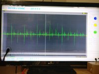
With no input, RCAs unplugged, or volume very low, the emitter and base have no square wave on them.
As the volume is turned up a bit, a square wave pops up on the scope. Is that square wave supposed to be audio?
I tried comparing the operating PDX1.600 to see if that could help me. The circuit is similar but I think it is a smd transistor used for this function in that amp. There is no square wave present on any terminals of that transistor while the amp is functioning normally.
Is the presence of that square wave a part of the problem?
Are you sure that you're checking the signal on the right, corresponding point in the 600 circuit?
Yes, you should see a signal.
I think, at this point, you would see the audio frequency when you are working on a non-functioning circuit. On a working amp, you'd see something closer to 80kHz.
Yes, you should see a signal.
I think, at this point, you would see the audio frequency when you are working on a non-functioning circuit. On a working amp, you'd see something closer to 80kHz.
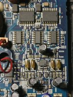
Would Q3305 and Q3304 be the corresponding transistors?
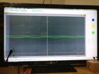
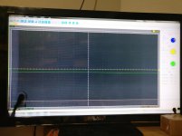
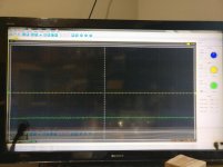
These are pics of what is on the three terminals of Q3305 with no signal, amp idling.
These are pics of what is on the three terminals of Q3305 with no signal, amp idling.
Attachments
No. You should see a square wave that swings fully between rails.
bcae1.com - Car Amplifier Repair Tutorial - The Basics
bcae1.com - Car Amplifier Repair Tutorial - The Basics
The 600 screenshots didn't show any of the waveforms I'd expect to see.
Maybe you need to drive a signal into the amp to get it to oscillate.
The transistors are used for muting but that's not all they do. They shift the drive level. Muting initially but level shifting during normal operation.
Yes on the 9701/2.
Maybe you need to drive a signal into the amp to get it to oscillate.
The transistors are used for muting but that's not all they do. They shift the drive level. Muting initially but level shifting during normal operation.
Yes on the 9701/2.
Where exactly should probe placement be for measuring oscillation on the outputs?
Regarding the level shifting, you said from the level of ground, to the negative rail. I assume the square wave I have shouldn't be there, so how is that ending up there?
Should I be seeing signal, at the level of the negative rail?
Regarding the level shifting, you said from the level of ground, to the negative rail. I assume the square wave I have shouldn't be there, so how is that ending up there?
Should I be seeing signal, at the level of the negative rail?
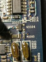
I removed Q303 and Q304. I tested the pads to see if that would help isolate the issue.
With the voltmeter, black probe on amp ground:
Q303. Q304
Emitter 5.03 5.03
Base. -0.67 -1.38
Collector -56.38 -56.38
With the voltmeter, black probe on the negative rail:
Q303 Q304
Emitter 61.42 61.42
Base. 55.79 55.07
Collector 0.00 0.00
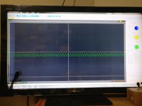
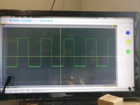
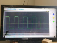
The scope shots are of the signal present on the base of Q303/304. The square wave is present when the signal is driven into the amp. With no signal, there is just a straight line.
It would seem to indicate that my issue may be related to the base connection. Is it that I am seeing a square wave when I should be seeing a frequency waveform similar to what is at E301/302?
Also, the voltage difference at the base is also a question I have.
With the voltmeter, black probe on amp ground:
Q303. Q304
Emitter 5.03 5.03
Base. -0.67 -1.38
Collector -56.38 -56.38
With the voltmeter, black probe on the negative rail:
Q303 Q304
Emitter 61.42 61.42
Base. 55.79 55.07
Collector 0.00 0.00
The scope shots are of the signal present on the base of Q303/304. The square wave is present when the signal is driven into the amp. With no signal, there is just a straight line.
It would seem to indicate that my issue may be related to the base connection. Is it that I am seeing a square wave when I should be seeing a frequency waveform similar to what is at E301/302?
Also, the voltage difference at the base is also a question I have.
Attachments
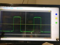
You must have a square wave.
The preamp part of the circuit before the level shifter is referenced to ground.
The class D drivers are referenced to the negative rail.
You have to transfer the preamp level signal to the negative rail. That's what the transistor does.
The signal on the emitter and collector will be approximately the same amplitude since the collector and emitter resistors are the same.
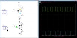
The attached is basically what you should have. The base is on a different generator so I could delay it. Otherwise it would be mostly hidden by the emitter waveform.
The preamp part of the circuit before the level shifter is referenced to ground.
The class D drivers are referenced to the negative rail.
You have to transfer the preamp level signal to the negative rail. That's what the transistor does.
The signal on the emitter and collector will be approximately the same amplitude since the collector and emitter resistors are the same.
The attached is basically what you should have. The base is on a different generator so I could delay it. Otherwise it would be mostly hidden by the emitter waveform.
Attachments
I went through the schematic checking all connections to Q303/304 collectors. With pin1 of IC304/306 lifted and D305/306 lifted, I still wasn't getting the square wave through. I flipped over the board and removed R316/317. This allowed some form of square wave through but I don't fully understand the science behind why. I assume the transistor not being turned on may have something to do with it. I am just searching for possibilities...
- Status
- This old topic is closed. If you want to reopen this topic, contact a moderator using the "Report Post" button.
- Home
- General Interest
- Car Audio
- Alpine PDX1.1000 powers on, no audio (IR2010s HELP)