If you don't have a square wave on that circuit, I don't understand it well enough to do any more. If I try to help with another one of these, feel free to remind me of the previous attempts.
I'll look in the shop when I go back in there but I don't remember any abandoned Alpine amps.
I'll look in the shop when I go back in there but I don't remember any abandoned Alpine amps.
Do Q9701/9702 in the MRP-M1000 operate with a square wave? I assume they are the level shifting transistors in that amp...
I was purposely not reminding you of your comment on another thread I came across, where you stated your intention not to help with another of these. Unfortunately, your limited ability with this amp probably far exceeds most others on this forum. If by some stroke of luck, or answered prayers, you get your hands on one and can help me, let me know. I won't be getting rid of it as I hope to resurrect it one day..
I was purposely not reminding you of your comment on another thread I came across, where you stated your intention not to help with another of these. Unfortunately, your limited ability with this amp probably far exceeds most others on this forum. If by some stroke of luck, or answered prayers, you get your hands on one and can help me, let me know. I won't be getting rid of it as I hope to resurrect it one day..
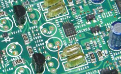
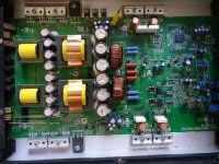
The amp arrived and has a defective IC that's not commonly stocked.
Working as it is, I found this.
The output of the op-amp IC9701 is a triangle waveform of about 1v p-p.
This drives the level shifter and the output on the collector is a bit less and no longer a triangle waveform. Much more rounded.
That drive pin 1 of the inverter. As it goes through the stages of the inverter, the signal gets more square and larger. Finally, on pin 6, it's about 12v in amplitude.
All of this is at the operating frequency (100kHz+).
So, the level shifter does transfer the signal as thought but at the operating frequency, the signals aren't square and are a very low amplitude.
I'll try tomorrow with the driver ICs disabled to see what the signal looks like as it passes through the circuit.
WITH THE DRIVER ICs DISABLED (pin 3 shorted to the lifted pin 13)
This is with a sine wave driven into the amp with sufficient level to drive IC9701 to clipping.
The output of 9701 swings about ±4v and is fairly square.
The collector of the level shifting transistor swings from the negative rail up about 8v.
The progression through the stages of the inverter don't change as drastically as when operating normally. They swing about 12v as when the amp is in normal operation.
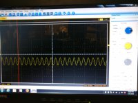
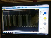
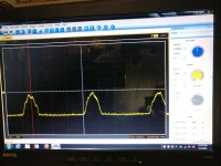
Pic1 is a pic of what is on Pin 1 of the NJM2137 and the emitter of the level shifting transistor in the working PDX1.600. It also makes it through the 1k resistor between these points intact. Is this the triangle waveform that is in your MRP-M1000?
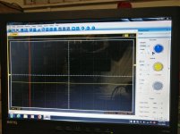
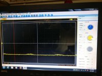
Pic2 is what is on Pin 1 of the NJM2137 in the non-working MRP-M1000 that I have and up to the 1k resistor.
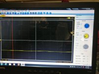
Pic 3 is what is on the other side of the 1k resistor onwards to the emitter of Q9701/9702. Is it that a square wave cannot pass through the resistor, but a triangle wave can? The resistor measures perfectly fine.
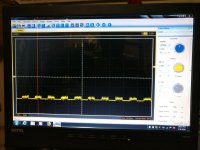
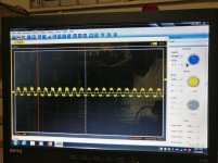
Pic2 is what is on Pin 1 of the NJM2137 in the non-working MRP-M1000 that I have and up to the 1k resistor.
Pic 3 is what is on the other side of the 1k resistor onwards to the emitter of Q9701/9702. Is it that a square wave cannot pass through the resistor, but a triangle wave can? The resistor measures perfectly fine.
Attachments
The PDX1.1000 uses 2 NJM2136 ICs while the M1000 and PDX600 both use a single NJM2137. The pinout is different and it would seem that 2 2136s act like a single 2137. There is no triangle wave in this amp. There is a square wave just like in the M1000 but in this amp, the square wave makes it through the 1k resistor intact all the way to the emitter and base of the level shifting transistor (2n5401). The 2 non functioning amps have square waves, while the functioning amp has a triangle wave at the emitter of the level shifting transistor. How come the square wave can pass through the 1k resistor intact in this amp, but can't in the M1000?
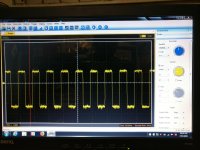
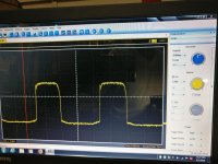
Pic 1 is the input to the NJM2136 ICs
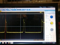
Pic2 is the output of the NJM2136 ICs and also on the emitter and base of the level shifting transistors.
Pic3 is the collectors of the level shifting transistors.
Pic 1 is the input to the NJM2136 ICs
Pic2 is the output of the NJM2136 ICs and also on the emitter and base of the level shifting transistors.
Pic3 is the collectors of the level shifting transistors.
Attachments
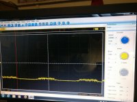
The output of the NJM2136 is basically a straight line of -4.2v up to about volume 24 on the deck. At volume 25 there are spikes that go from -4.2v to +4.2v. Just reporting what is happening in the PDX1.1000 as compared to what is happening in all the other amps.
Attachments
With the ICs disabled in the M1000, the NJM2137 behaves just like the PDX1000 up to the 1k resistor before it reaches Q9701/9702 emitter. It is a -4v flat line that starts to spike upwards at approximately volume 23. There is still very little rise to the waveform on the other side of the 1k resistor. At volume 45 the output of NJM2137 Pin1 is more of a square wave with a rounded dome, but it still remains negatively flat after the 1k resistor.
Attachments
- Status
- This old topic is closed. If you want to reopen this topic, contact a moderator using the "Report Post" button.
- Home
- General Interest
- Car Audio
- Alpine PDX1.1000 powers on, no audio (IR2010s HELP)