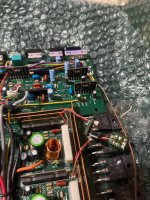
Hello! I’m planning to rebuild an 3553 alpine that I’ll be using for midrange and tweeters. Till now I changed the power supply caps and voltage regulator pair of transistors tta-ttc, 2 Zener diodes. My question is on the signal path per channel I have 10uf , 100uf BP and 0,47uf. The 100uf I used muse BP , on the other hand I ordered wrong some Panasonic fc that are tiny(miniature) and nichicon uep BP. Now I put the Panasonic fc in the place of 10uf. It is a good ideea or I have to order some new ones? Seems impossible to find good 10uf for audio path. Also I ordered sip adapters for njm and I will replacing with opa2134. Some caps are a little bigger than original and stay on some resistors, is this gonna be a problem? Any advice is well regarded.


I'll get hammered for this but... all of this is a waste of time. Audio capacitors are a scam. If you make 10 such mods, it will be impossible to tell the difference between a stock amp and a modded amp. The only possible difference will be a slightly lower noise floor but that's rarely a problem unless you're using it for headphones.
Use the original values components and you will be OK.
If there were defective caps that leaked electrolyte, you need to scrub the board well with cotton swabs and acetone.
Don't let this stop others from helping you. This is my opinion.
Use the original values components and you will be OK.
If there were defective caps that leaked electrolyte, you need to scrub the board well with cotton swabs and acetone.
Don't let this stop others from helping you. This is my opinion.

Omg, you’re so well regarded in the audio community and replayed to me. Thanks! My questions are : it is opa2134 a good replacement ? Also I’m planing to add 100pf on them and change the oscillator resistance from 18k to 13k to switch the spike at 16khz from the power supply. The resistor have to be special? Low tolerance? Low coefficient ?
The only cap that was somehow burned was in the voltage regulator section, that’s why I changed the 2 transistors and 2 Zener and all caps.waste of money it is as the amp was 60euro and I ordered parts 3 times and got over 200euro 🙂
I don’t want to improve it, because I cannot design an amplifier, I just want that the amp perform as was designed to and be sure that I used high quality parts and reliable ones.
Attachments
Last edited:
I don't think I understand all of the questions.
The opa2134 a good replacement? For what? How are the originals so offensive that they need to be replaced?
Not all op-amps work well in all circuits. Some, especially for those not unity-gain stable most are but some may oscillate at a very low level (barely audible) in some circuits.
Adding 100pf where?
Are you referring to the power supply oscillator? What problem, specifically, is it causing?
For oscillators like those in the power supply, especially in this amp, there is nothing that wouldn't work. In general, low temperature coefficient is good, low tolerance is good. The timing resistor, not critical. The switching power supply is so well filtered that none of this is a real concern. If you want to use tighter tolerance parts, low coefficient parts, it won't do any harm but in a double-blind A/B test, there would be no audible difference.
Let me say that I have no problem with people replacing perfectly good parts. What I don't like/want is someone leading you around by the nose (I don't know if that will translate well) telling you to do all sorts of mods and then telling you you have tin ears if you can't hear the wonderful difference old and new.
Opa2134 replacement for njm4580l , the buffer amps, adding a 100pf ceramic capacitor on v+ and - legs of the opa. I changed the parts because this amp it’s made in the 90 and I know that capacitors are losing properties over time.
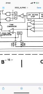
The power supply on this amps have a noise spike at around 16khz from the psu switching frequency(I think).
The power supply on this amps have a noise spike at around 16khz from the psu switching frequency(I think).
At one time, I felt like an idiot because I wasn't replacing caps like so many were saying was absolutely essential. To know what to change, I purchased a good capacitor tester (Sencore LC102) and started checking caps in every amp I had come into the shop. Virtually none were defective and most all were perfectly withing tolerance except the ones that were obviously leaking electrolyte. There are some problematic amps and sometimes just a few caps in other amps but don't assume that age will make every electrolytic capacitor fail.
You think? That's not a good way to make decisions. Where did you get this information?
The oscillator frequency is approximately 50kHz with the drive output being 25kHz. Where does the 16kHz come from?
Is it getting into the audio?
I don't know where you found the 100pf value. If the newer op-amps need more capacitance that wouldn't be bad but, for most all local bypass duties, a 0.1uf capacitor is connected between the supply pins and ground. This is generally good but not if the layout didn't anticipate power supply bypassing (was intended only for audio).
Some sort of added bypassing with caps may be necessary but you (everyone) should understand that not everything works in every situation.
I don't think you realize what 80dB down is. Add to that that this is at 16kHz, and it's a non issue. Someone should correct me if this is wrong but this is equivalent to an amplifier producing 150w and having a noise that's producing 1 millionth of a watt... at a frequency where you can barely hear anything.
Turn your volume to a very low level before opening the following file.
Turn your volume to a very low level before opening the following file.
Turn your volume to a very low level before opening the following file.
https://www.bcae1.com/temp/0dbneg40dbneg80db.flac
This is approximately full volume for 4 seconds then the same tone at -40dB for another 4 seconds and finally the same tone at -80dB. This is 1k and far more audible than 16kHz. Does this help you to understand the magnitude of the problem with a 16kHz signal being 80dB down?
Yes, I understand that is down in the noise, but if I can move it with no real downsides, I will do it.
Check the actual frequency of the PS drive to see where it's at. The timing components may have drifted in value. Otherwise, I don't see a 25k oscillator producing a 16k spike.
When driven hard, the caps between the rectifiers and the inductors may be stressed more. The PS transistors are not FETs. They are BJTs. The higher frequency may be more stressful on them and the driver circuit.
When driven hard, the caps between the rectifiers and the inductors may be stressed more. The PS transistors are not FETs. They are BJTs. The higher frequency may be more stressful on them and the driver circuit.
I have but I realised I don’t have a battery to be able to turn on the amplifier. The first test will be on car.
Worked 2 days, had some colder joints on some ic, resolder everything , was on mute and it send dc on one channel, I think it broke a tweeter , I tried to test it using a good channel and a probe from an rca , it have a buzzing sound all the time, if I touch the rca it have sound , touched the first ic in the chain , on the input it makes a louder sound and on the output pin it just stop all the sound. I don’t have the expertise or a scope, I don’t have hope anymore.
Are you asking for help or simply closing out the thread, given up on the amp?
Side note, never connect tweeters dorectly to an amp unless you can afford to have them be blown. DC on the output of a failed amplifier is common and a capacitor inline with the tweeter (even if you have a crossover built into the amplifier) helps protect it,.
Side note, never connect tweeters dorectly to an amp unless you can afford to have them be blown. DC on the output of a failed amplifier is common and a capacitor inline with the tweeter (even if you have a crossover built into the amplifier) helps protect it,.
I’m asking for help if you think I can make it reliable, what I find yesterday : gain at min- loud harsh sound , I raised the gain a little no sound but crackling . Channel 2 have same sound also .
I have an rca with a cap as probe and a multimeter, most surely have dc because on the tweeter it pulled the membrane and after I check it , I put in on car with a midbass to test that channel, as soon as I start the amp , stays like 2 seconds then start to make serious excursion .all I did yesterday I check continuity and resolder the rca on the rca board , I didn’t have continuity in the connector all the time so I think it’s an easy fix. What I also notice when testing the channel is if I touched on the output on first ic , the membrane of the midbass moves one time and was silent.
- Home
- General Interest
- Car Audio
- Alpine 3553