Check it with your meter or tester to see if reads like the one you pulled.
You can try it in the circuit.
You can try it in the circuit.
With a faulty Q318, the voltage on the uPC494C was:
1. 0V
2. 4,72V
3. 93,8mV
4. 4.72V
5. 1,62V
6. 3,63V
7. 0V
8. 14.4V
9. 0V
10. 0V
11. 14.4V
12. 14,4V
13. 4,87V
14. 4,87V
15. 4.87V
16. 0V
Power consumption 0A.
When replacing 2SB1076M with TIP107, the voltage on uPC494C became:
1. 0V
2. 4,72V
3. 91,7mV
4. 10,2mV
5. 1,61V
6. 3,61V
7. 0V
8. 14,16V
9. 5,93V
10. 5,92V
11. 14,15V
12. 14,15V
13. 4,87V
14. 4,87V
15. 4,87V
16. 0V
Power consumption 1A.
But there is still no sound.
1. 0V
2. 4,72V
3. 93,8mV
4. 4.72V
5. 1,62V
6. 3,63V
7. 0V
8. 14.4V
9. 0V
10. 0V
11. 14.4V
12. 14,4V
13. 4,87V
14. 4,87V
15. 4.87V
16. 0V
Power consumption 0A.
When replacing 2SB1076M with TIP107, the voltage on uPC494C became:
1. 0V
2. 4,72V
3. 91,7mV
4. 10,2mV
5. 1,61V
6. 3,61V
7. 0V
8. 14,16V
9. 5,93V
10. 5,92V
11. 14,15V
12. 14,15V
13. 4,87V
14. 4,87V
15. 4,87V
16. 0V
Power consumption 1A.
But there is still no sound.
It was driving pin 4 high, shutting the IC down.
Could this transistor have been damaged after your initial post?
Are the 3 muting transistors still out of the circuit?
Could this transistor have been damaged after your initial post?
Are the 3 muting transistors still out of the circuit?
Perhaps it was damaged after my first message. Three muting transistors are on the board, I have not tried to solder them all at once, only one by one. Is it worth trying to remove these three transistors and check the sound?
Please (and this applies to anyone who needs repair help) use your sig line to list all equipment you have, editing it as equipment changes. Include the model numbers. If you can't do this due to being a new member, make a list in the next post.
Top of page, menu USER CP >> EDIT SIGNATURE
Oscilloscope (yes or no)
Multimeter(s)
Type of signal source (grounded RCA shields preferred).
Soldering iron
Desoldering pump
Power supply
2 ohm current limiting resistor (hollow cylindrical ceramic 100w preferred)
Top of page, menu USER CP >> EDIT SIGNATURE
Oscilloscope (yes or no)
Multimeter(s)
Type of signal source (grounded RCA shields preferred).
Soldering iron
Desoldering pump
Power supply
2 ohm current limiting resistor (hollow cylindrical ceramic 100w preferred)
You will need to try to trace the signal through the amp. This would be easier with a scope or with a signal tracer but you may be able to do this with a multimeter.
Set your meter to 2v AC. Set the volume on the head unit high. Go between mute and normal audio. Be sure that you can see the change at the RCA jacks on your meter. Go from point to point along the circuit path to see where the signal is lost.
Set your meter to 2v AC. Set the volume on the head unit high. Go between mute and normal audio. Be sure that you can see the change at the RCA jacks on your meter. Go from point to point along the circuit path to see where the signal is lost.
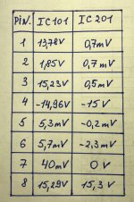
I found a faulty resistor in the -15 volt R328 power supply circuit, after replacing it, the sound appeared in both channels. But I am confused by the voltages on IC101 and IC201, they differ from those indicated in the service manual. Here's what I measured:
IC101
1. 15,15 V
2. 47 mV
3. 5,4 mV
4. 5,2 mV
5. -14,9 V
6. 15,2 V
7. 1,85 V
8. 13,85 V
IC201
1. 15,25 V
2. 0 V
3. 0 V
4. 0 V
5. -15 V
6. 0,5 mV
7. 0,2 mV
8. 0,7 mV
On the rest of the microcircuits, the voltage is normal. It is also necessary to measure the voltage across the transistors according to the service manual.
You have the pin configuration wrong. Repost the numbers.
https://datasheet.octopart.com/UPC4570G2-E1-A-Renesas-datasheet-138184105.pdf
https://datasheet.octopart.com/UPC4570G2-E1-A-Renesas-datasheet-138184105.pdf
That's the first time that I've seen that sort of error but looking at the diagram again, I can see what you did.
I wouldn't expect the amp to produce audio in this condition. Is the amp in stereo mode?
If so, does the voltage on pin 1 of the 4570 change significantly is you switch from fixed gain to variable gain?
I wouldn't expect the amp to produce audio in this condition. Is the amp in stereo mode?
If so, does the voltage on pin 1 of the 4570 change significantly is you switch from fixed gain to variable gain?
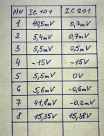
The amplifier is in stereo mode, and when I switch the fixed gain to variable gain, the voltage at pin 1 4570 changes from 40,5 mV to 20 mV;
I don't think the amp could have had audio on both channels if the amp is in stereo mode with 15v on pin 1.
The numbers on the service manual won't be exactly the same. Which voltages are you concerned with?
The numbers on the service manual won't be exactly the same. Which voltages are you concerned with?
- Home
- General Interest
- Car Audio
- Alpine 3542 no sound