Gable,
Texas has similar temperatures to southern Australia so we share heatsink issues.
Ciao,
HD
So I hear, and I hope to experience some day, sooner than later, and hopefully in NSW, at a little place called Mount Panorama .... 🙂
I'm a little bit of a sports car racing fan... also, I hear Australia is a lot like South Texas, just 1000 times bigger., and .. more.... this appeals to me.
I really want to camp at the race, and spend a few days drinking in the outdoors with locals... surprisingly enough my wife doesn't have the same idea of fun....
Hi Pcgab,
Hugh is right, use one 8in x 10in heatsink per MOSFET. So four of those and a separate heatsink for SLB and you are good. I used the 6224 for the AN and it was perfectly sized to give you 28.5v which is actually a solid 41w I think.
We have a soft start coming soon. I have built gen 1 but found it could be improved so waiting for gen 2 PCB to arrive. It uses a low RDSon SSR to bypass four 100ohm resistors in parallel. Probably 3 weeks away from being available for sale.
This is good news, I'll order another pair of the heatsinks when they get them back in stock.
Thank you sir!
I really want to camp at the race, and spend a few days drinking in the outdoors with locals... surprisingly enough my wife doesn't have the same idea of fun....
Looks like you two are a perfectly normal couple! 😀
Mount Panorama
My favorite track on Forza 7 with a Lancia Stratos HF, and I bet very fun in any car in real life.
Hi pcgab,
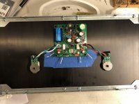
I’m using a Dissipante 5U 400 chassis for my AN.
It’s 210mm x 400mm heatsinks keep the temps a bit below 50°C with 28vdc @ 1.65mA bias.

Nice short leads and it looks like someone upgraded a cap.

Hi pcgab,
I’m using a Dissipante 5U 400 chassis for my AN.
It’s 210mm x 400mm heatsinks keep the temps a bit below 50°C with 28vdc @ 1.65mA bias.
That fits nicely. I like the remote boards with smt snubber, very clever. Lots of heatsink for one device!
My favorite track on Forza 7 with a Lancia Stratos HF, and I bet very fun in any car in real life.
I bet driving a Stratos...on any track would be an amazing experience... crazy little maniac of a car.
Sorry for OT ... 🙂
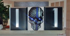
Left AN Done
Here's a shot of the outside of the left channel of the AN, still waiting for a case for the right. The right side skull will have a red strip and red eyes.
The cell phone snap doesn't do it justice. I can't wait to see them side by side and give them a listen.
Here's a shot of the outside of the left channel of the AN, still waiting for a case for the right. The right side skull will have a red strip and red eyes.
The cell phone snap doesn't do it justice. I can't wait to see them side by side and give them a listen.
Attachments
Last edited:

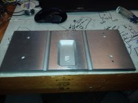
Brilliant machine work. Aluminium? Anodised?
Really nice appearance for a great amp........
Hugh
Really nice appearance for a great amp........
Hugh
Thanks guys, I didn't machine that, though I do want anodized one with laser etching the etch will show through as aluminum. This was more of a test to see if I liked the look. It's not machine work, but carbon fiber wrap, like what they use for cars. If I didn't like it simply peel it off.
There is also and aluminum plate bonded to the front because I didn't like the switch area where it was milled out and it wasn't wide enough to accommodate the eyes. I really like the look and will be doing some laser engraving test of both anodized and non going forward. I'm, also looking at some milling options as I have access to some rather nice CNCs.
In fact, the owner of the shop might be interested in machining some cases. I think it would be nice to have some form of control over the process, in which, we can address some issues what is available to us now. We would have the added benefit to change the design on the fly, much as JP does for layouts. One of the big problems with current manufacturers, is they don't care to make changes.
JP, you want to do some layouts for chassis?
Last edited:
What we need in the case business, is someone like JP, who embraces enhancements.
+1... but custom work on metal can be expensive.
JT,
Kudos on the case - nice look you got there! Good idea with going with carbon fiber wrap, and you can make the final version in aluminum once you're satisfied.
Last edited:
Hi pcgab,
I’m using a Dissipante 5U 400 chassis for my AN.
It’s 210mm x 400mm heatsinks keep the temps a bit below 50°C with 28vdc @ 1.65mA bias.
I am a bit surprised that the heatsinks are that hot at 1.65 mA 😉
Best,
Anand.

I'm still closer to you Vunce. I typically apply a drop of solder to one pad, heat it and slide the component into the molten solder. A little downward pressure with the tweezers gets it flat to the board. Then apply solder to the other pad. I will admit to having a good ERSA temperature controlled soldering iron and use the smallest chisel tip available. And I prefer leaded solder.
I've been trying to follow your method, jh - this is the first time I've soldered SMDs ... and I don't like it! 🙁
How do you decide if you have a good solder joint between the cap on each end of a capacitor, for example, and the pad on the PCB?
I've been putting my meter leads on the through-hole pads which belong to adjacent components which connect to the soldered SMD ... and if it reads correctly ... I'm assuming it must be OK? 🙁
Andy
A good solder joint will have a nice fillet. If you can see a black line (crack) separating the component from the pad it’s probably a cold solder joint.
Vunce just did his very first SMT project to practice his soldering skills and I must say, he is a master already. Check out his work here on the PCA (pocket class A) headphone amp.
xrk971 Pocket Class A Headamp GB
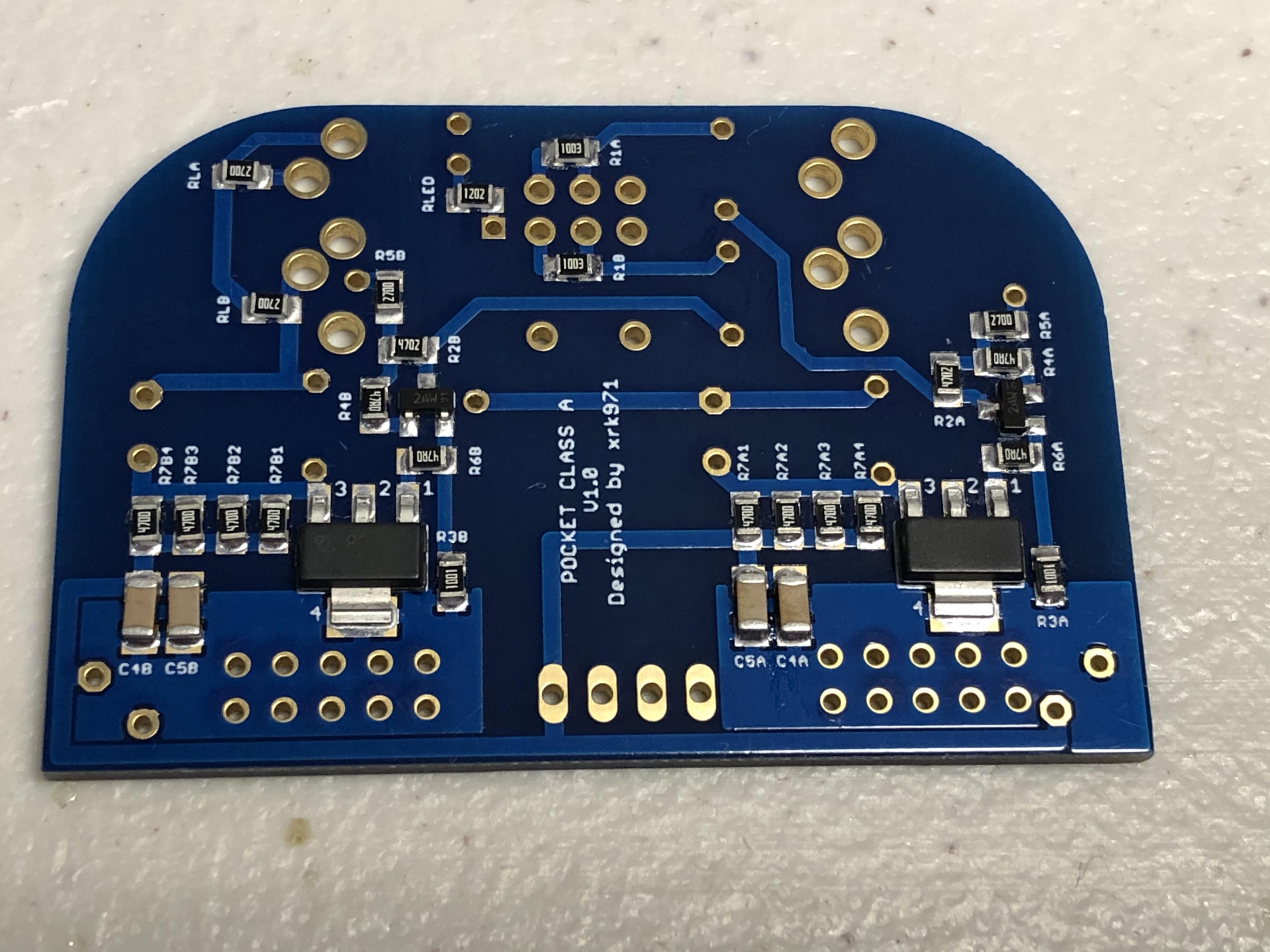
Yes, but check for cold solder joint. If suspect, just retouch with iron for a second to reflow it. Solder paste works incredibly well vs standard “string” solder.
Vunce just did his very first SMT project to practice his soldering skills and I must say, he is a master already. Check out his work here on the PCA (pocket class A) headphone amp.
xrk971 Pocket Class A Headamp GB
I've been putting my meter leads on the through-hole pads which belong to adjacent components which connect to the soldered SMD ... and if it reads correctly ... I'm assuming it must be OK?
Yes, but check for cold solder joint. If suspect, just retouch with iron for a second to reflow it. Solder paste works incredibly well vs standard “string” solder.
Last edited:
- Home
- Amplifiers
- Solid State
- Alpha Nirvana 39w 8ohm Class A Amp