I would recommend thermal paste with the ceramic pads, that’s the setup I use and it works very well. Temperature taken with an IR gun, the AN Mosfets don’t get above 65°C.
It’s a little messy but I feel worth the extra step.
Hi Vunce, what are 'ceramic' pads? So far, I've used mica pads ... with thermal paste.
I'm curious to know what the advantage is of 'ceramic' or 'silicon' pads is.
Thanks,
Andy
Aluminum Oxide “ceramic” pads are excellent for electrical insulation and have superior thermal conductivity characteristics compared to mica and silicone.
Since they are rigid, use thermal paste when installing. They could crack from over tightening, but I’ve yet to have that happen.
Since they are rigid, use thermal paste when installing. They could crack from over tightening, but I’ve yet to have that happen.
Tests have shown that aluminum oxide or “alumina” ceramic spacer pads with thermal compound, beats everything except bare metal-to-metal contact. Beats mica, silicone, Kapton, etc. it’s also very robust. I accidentally forgot to turn the fan on my CPU cooler on once and it worked overnight without melting. The amp still worked with 24hrs later no fan - this is 160w into the Dell FD heatsink. I don’t recommend this though. 🙂
Aluminum Oxide Ceramic - Aavid, Thermal Division of Boyd Corporation - Pads, Sheets | Online Catalog | DigiKey Electronics
I have some that can fit TO-264 or TO-3P.
Example of how it’s installed on Alpha BB amp:
Aksa Lender P-mos Hybrid Aleph (ALPHA) Amplifier
Aluminum Oxide Ceramic - Aavid, Thermal Division of Boyd Corporation - Pads, Sheets | Online Catalog | DigiKey Electronics
I have some that can fit TO-264 or TO-3P.
Example of how it’s installed on Alpha BB amp:
Aksa Lender P-mos Hybrid Aleph (ALPHA) Amplifier
Last edited:
Tests have shown that aluminum oxide or “alumina” ceramic spacer pads with thermal compound, beats everything except bare metal-to-metal contact. Beats mica, silicone, Kapton, etc. it’s also very robust. I accidentally forgot to turn the fan on my CPU cooler on once and it worked overnight without melting. The amp still worked with 24hrs later no fan - this is 160w into the Dell FD heatsink. I don’t recommend this though. 🙂
Aluminum Oxide Ceramic - Aavid, Thermal Division of Boyd Corporation - Pads, Sheets | Online Catalog | DigiKey Electronics
I have some that can fit TO-264 or TO-3P.
Example of how it’s installed on Alpha BB amp:
Aksa Lender P-mos Hybrid Aleph (ALPHA) Amplifier
Thanks, X.
That link you posted has 5 different-size ceramic insulators. You said the ones you have, fit TO-264 & TO-3 as well as TO-220 (so I guess you bought 4180G)?
But any of the others that say 'TO220' would be suitable, right?
Regards,
Andy
The bigger the better,
the contact area with the heatsink becomes bigger
First off, I thought "that makes sense"! 🙂
But thinking a bit deeper, I'm afraid I have to question whether a larger insulating pad does actually enable more heat to be transferred to the heatsink?? The area of the insulating pad directly under the body of the MOSFET is compressed against:
* the MOSFET
* and the heatsink
... by either a bolt through the MOSFET or the CPU cooler pad fixing bolts - so heat passes into the heatsink very well.
But the portions of the insulating pad that are not directly under the MOSFET will not be bonded to the heatsink to the same degree. So the heat transfer will not be as good (as directly under the MOSFET)?
Regards,
Andy
Yes, it is area underneath and has to be at least as large as the body of the active. TO-220 and TO-247 too small for TO-264 or TO-3P. I think I got the 22mm x 28mm x 1mm ones from eBay.
10 pcs Ceramic Sheets TO-3PL 22x28 T0.6 / T1.0mm Transistor Heatsink Pads | eBay
10 pcs Ceramic Sheets TO-3PL 22x28 T0.6 / T1.0mm Transistor Heatsink Pads | eBay
Alumina is extremely hard, and we're talking about a few mm wider pads than the mosfet,
so the 1mm thick ceramic won't bend at the edges.
The pressure will be almost the same at the edges, especially when used a bar over the mosfet.
so the 1mm thick ceramic won't bend at the edges.
The pressure will be almost the same at the edges, especially when used a bar over the mosfet.
In case you wonder how to connect the wires on the flying leads to the Molex quick conencts and the MOSFETs.
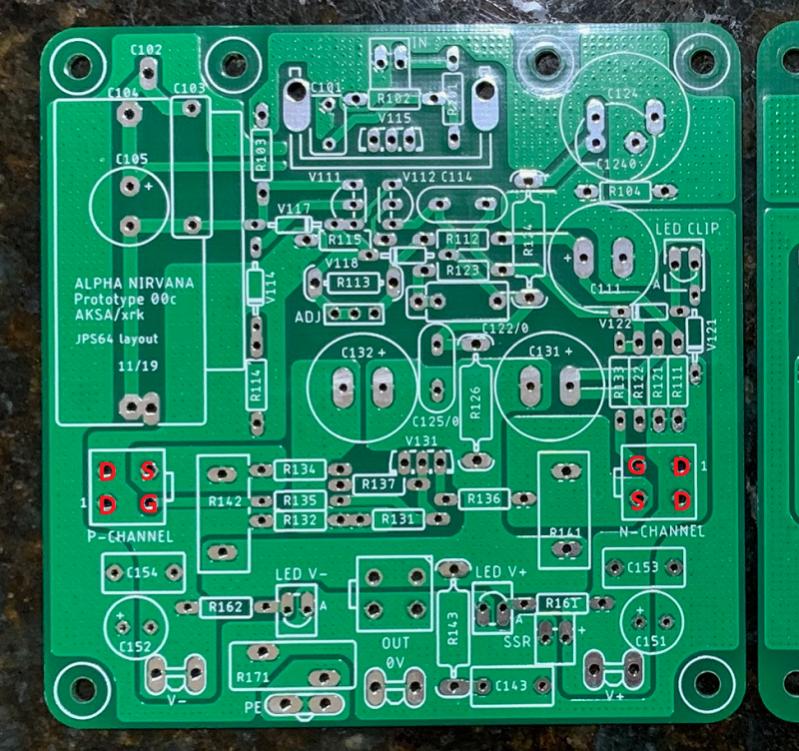
Drain goes to PSU input spades. Source goes to Source resistors. Gate is the small trace.
For build related or troubleshooting questions, I think posting in the GB thread might be more appropriate. This thread is for general discussions of the circuit topology, performance, listening impressions etc. But if you don't find what you are looking for here, don't forget to check the GB thread, which has not seen too much usage.
Alpha Nirvana 39W SE Class A Amplifier GB
Last edited:
Well, I wish I could say it went well, but it wasn't even close. One side was working for a bit and the other was not, now it's pretty much hosed. I thought I had it figured out, so I used the other side to check that out and now I have a few hundred worth of modern art.
No magic smoke or any fireworks, just no values that look right anywhere. Even with the FET disconnected nothing I get different voltages from the outputs of each.
I had to troubleshoot the supply and now this mess, for now, I need to get away from it for a bit as all I feel like doing now is firing it in the ash can.
Very few things can blow out so if all the resistors are correct, just replace the actives. Test your MOSFETs and if they don’t measure below tens of kOhms between pins - they are probably still good. If they read 0 to 10ohms they are toast. But this would have caused fireworks when plugged in. Since you did not have any smoke or excitement I bet your MOSFETs are still good. You have a wiring error somewhere. If the gates are not at say 22v on the N channel and circa -22v on the P channel, something upstream is off. Sometimes you can have a bad electrolytic cap that is shorted.
Verify the pin out from the MOSFET to the board. Trace each wire and follow the diagram for pins on the Molex that I posted. Be sure you have P channel on P and N channel on N connectors.
We will help you debug it if you can provide a redlined schematic with all nodes measured relative to 0v like I asked. You marked it up but the values did not make any sense. Please use decimal Volts like 22.5v or 0.56v. Avoid mV unless you know that you are indeed in mV mode. Make sure you are using DC volts not AC volts.
Without the diagram of node voltages we have no idea how to diagnose other than to say go back and make sure there are no cold solder joints and no inadvertent solder bridges.
Since you said you checked the values of the resistors already we will assume those are correct.
So the only thing that can be the problem are cold solder joints or solder bridges. Or bad transistors or capacitors.
The input LTPs generally never go bad or get burned out. You can check them if they flow about 2mA through the resistor above them.
The main MOSFETs will make music if there is bias current. There will be bias current if the gate voltages are correct and the main PSU rail connectors are connected.
There will be gate voltages if the small signal transistors and their resistor networks are correct.
This is a no adjustment amp so it relies only on correct parts placement and avoidance of poor joints. It will work guaranteed when the components are correct and properly soldered.
Last edited:
X, what torque do you use when tightening the screw when using the 1mm ceramic insulators?
They look like they will crack if tightened too much.
Maybe the spec sheet will have these details.
They look like they will crack if tightened too much.
Maybe the spec sheet will have these details.
X, Vunce - I've found I can buy ceramic pads in Oz cheaper than the price shown on that eBay link you provided (from RS Components).
Now, that eBay link gave you an option of 0.6 or 1mm thick; is it "thinner the better at heat transfer" ... or thicker is better?
Why I ask is that the thermal pads that RS sells, range from 1.5mm to 4mm thick (with the difference in pad sizes) - so do I choose the thicker ones ... or is 1mm optimal, in which case, I'll buy the eBay ones.
Andy
I don’t know the torque - I use a Bhondus hex ball driver on a M3 hex cap screw. Two or three fingers snug tight. You will strip the aluminum heatsink threads before you break the ceramic - it’s the same stuff they make ceramic knives from. The screws need to be tight for good thermal contact. Don’t reef down on it. If I were to guess based on what I know about torque settings on bike handlebar stems - about 0.5 Nm or less. Not much.
Andy,
The thermal conductivity shows the same (20W/m·K) for both the RS-Online 2mm pad and the eBay 1mm items. I see the name brand ones are 2mm thick (e.g. Aavid), probably to make it less fragile.
The thermal conductivity shows the same (20W/m·K) for both the RS-Online 2mm pad and the eBay 1mm items. I see the name brand ones are 2mm thick (e.g. Aavid), probably to make it less fragile.
Andy,
The thermal conductivity shows the same (20W/m·K) for both the RS-Online 2mm pad and the eBay 1mm items. I see the name brand ones are 2mm thick (e.g. Aavid), probably to make it less fragile.
That's very interesting, zman. 😎 I hadn't understood what that number meant.
However, I notice that all the different thermal pads on this RS Components page:
https://au.rs-online.com/web/c/hvac-fans-thermal-management/electronics-heating-cooling/thermal-pads/?searchTerm=ceramic%20insulator%20pads&redirect-relevancy-data=636F3D3126696E3D4931384E53656172636847656E65726963266C753D656E266D6D3D6D61746368616C6C7061727469616C26706D3D5E2E2A2426706F3D31313326736E3D592673723D2673743D43415443485F414C4C5F44454641554C542673633D592677633D4E4F4E45267573743D636572616D696320696E73756C61746F722070616473267374613D636572616D696320696E73756C61746F72207061647326&r=f&searchHistory=%7B%22enabled%22:true%7D
all show '20Wm K' - whether they're 1.5mm thick ... or 4mm thick. Which doesn't make sense! 😕
Andy
Mine are 1mm thick and I've never broke one.
The thermal conductivity of the 1mm alumina pads is very high, see page 25 in EUVL's article for a comparison of different pads with 1mm thick alumina.
The thermal conductivity of the 1mm alumina pads is very high, see page 25 in EUVL's article for a comparison of different pads with 1mm thick alumina.
Mine are 1mm thick and I've never broke one.
The thermal conductivity of the 1mm alumina pads is very high, see page 25 in EUVL's article for a comparison of different pads with 1mm thick alumina.
Thank you Danny for providing the link to hard data.
Surprisingly, Kapton and even mica rank as electrical folkore!
Mine are 1mm thick and I've never broke one.
The thermal conductivity of the 1mm alumina pads is very high, see page 25 in EUVL's article for a comparison of different pads with 1mm thick alumina.
Very interesting, danny - thanks. 🙂
That shows 'keratherm 86/82' is the go! Googling this, I come up with this company:
https://neurochrome.com/products/keratherm-red-86-82?variant=30106665156678
The table on p25 shows that although the thermal conductivity is only 1/4 of a 1mm thick ceramic pad, it measures significantly better for:
* deg C/W, and
* dT @ 32W.
And it's not rigid!
They rate it better than ceramic (and mica!)
Andy
- Home
- Amplifiers
- Solid State
- Alpha Nirvana 39w 8ohm Class A Amp