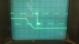
It's hard to tell. I would say the right one on second photo is real - given the clean satin finish legs and clean epoxy casing. Use a vise to crack it open and look at the die. Compare to die on a known real one (crack open a dead genuine). Usually, fakes are sloppily mounted at odd angles, look visually smaller, and have white RTV silicone on them.
I have play some with the amp.
The only way to get stable action except the thermal runaway who is not that big a issue I have removed the two irf610 mosfets and lower the R25 and R26 resistors to 150 ohm, this do track the capacitance very well with enough current, the CCS version has a way to high impedance making the capacitance of the irfp240 a issue with give instability and even oscillations. I have now idle the drivers on 25 mA and do well.
another thing is the voltage need no 2 x 35 volts, only the positive one needs that and the lower one only 12 volts or so, I have 50 volts, very low distortion but I do not now quality, for the irfp250n these is not really good sounding ones.
regards
Attachments


That looks good Kees. Are you bypassing entire IRF610 driver section. And driving from input stage JFETs?
I wanna ask how you mean in series with the drains U3 U4 etc, have you a kind of drawing for me because the amp did protest on my way.
This drawing is conceptual, but I hope it will better explain what I had in mind.
Attachments
That's sad to read- crime Fakers.
The newer IR have satined legs- my Mousers.
The older, bought here from reichelt, have tinned glossy legs, but yes the real logo
should be the right one.
Kees i have also bought from TME some IRFP150- looks good too and genuine ones.
The newer IR have satined legs- my Mousers.
The older, bought here from reichelt, have tinned glossy legs, but yes the real logo
should be the right one.
Kees i have also bought from TME some IRFP150- looks good too and genuine ones.
That looks good Kees. Are you bypassing entire IRF610 driver section. And driving from input stage JFETs?
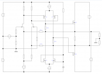
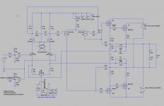
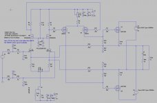
this is the schematic I did use, changing the ccs by removing them because of no use in a circlotron, just eat current away and act as a overcompensated Vbe.
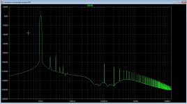
I have two types, one with driver outside the circlotron and one who has a source follower inside the circlotron so the LTP is not load with a big capacitance because now I use small mosfet to driver the source follower, however now we need more input voltage for same output voltage and it is better to change the supply to 50 volts or such, and the minus can just be 15 or 12 volts because we need some negative voltage for the ltp CCS, resistor do not work well here because of unbalance, for Joe can I here also change the dc path for the feedback?, I have no offset problems because in circlotron both ends has some volts of the same size..
The extra driver version do as you see have a lot less HD or almost nothing left on 10 watts. The second version has more, because of non liniair capacitance mosfet irf9610 who load ltp. here I can try later today a small cascode mosfet above the irf9610 and see what happens, capacitance is than a lot lower as cascodes do.
regards
Attachments
Last edited:
I have a transistor as a temp sensor, with base tied to collector, however it overcompensates, has somebody a idea to change this for example with a resistor paralell over transistor or emittor degeneration etc.
This drawing is conceptual, but I hope it will better explain what I had in mind.
Thanks Joe now I do see what you mean, I have to say the offset is not a problem with the amp it cancels itselfs out in this amp.
I have change yesterday the amp by removing the two irf 610 mosfets, these do nothing in this circlotyron amp except make idle unstable, as I see it looks now a little like what you do mention in your drawn, who looks very good, I go sim this to see what happens.
The version with the extra mosfet in the output circlotron is proberly a better way to do things, because now the LTP get not so much capacitive loaded be big power mosfets like the irf9610, or maybe a cascode to cancel out capacitance can work.
so much ideas and possibillities, like the full cascoded amp in picture.
regards
I have a transistor as a temp sensor, with base tied to collector, however it overcompensates, has somebody a idea to change this for example with a resistor paralell over transistor or emittor degeneration etc.
I have seen an LED added in series with a BD139 to correct for the overcompensation.
I have seen an LED added in series with a BD139 to correct for the overcompensation.
Yes but the current through the VAS is 70 mA total and this will proberly kill the led.
Joe
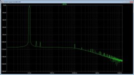
I have sim your other way of feedback, the positive is because on top of a ccs there is a 1 volt voltage who stays that way because of ccs keeps constant current who give a stable voltage also on feedback point, other then on output who has 4,12 volts on both sides who by the way do also work fine, the offset was never a problem because it cancels out.
For distortion it do better, special at higher output powers.
thanks for idea.
kees
Attachments
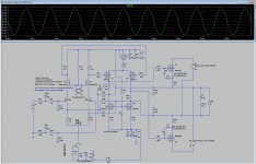
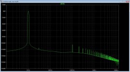
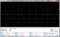
I have measure now the amp, looks like I have what I need and sounds oke to, the problem however with the idle current compensation needs attention, because I need a positive correction and not negative I need advise, I can correct it on the ccs, with a temperaure sensitive resistor, (NTC) or (PTC) then we can track it on a fast way but needs the sensor on the mosfets irf240/250.
The input square is the input and the output of the amp, so you can see it is just the same input as output who means it do amplifie well.
I have measure with a pc card, and arta, I think here go things not 100 procent right, maybe a better audio card and not in build in audio I do use.
regards
The input square is the input and the output of the amp, so you can see it is just the same input as output who means it do amplifie well.
I have measure with a pc card, and arta, I think here go things not 100 procent right, maybe a better audio card and not in build in audio I do use.
regards
Attachments


Put the NTC 5k thermistor and 2k in series across the inputs to the OPS driver section gate inputs and supply rail. A negative tempco response will slowly "short" the gate on the driver and reduce voltage, hence bias on outputs. This is what was done on my Juma F5. Seems to work.
we need not to disturb the opposite fase respons because this need the circlotron to get balanced but I can try.
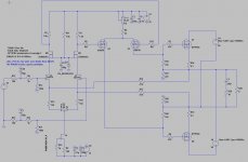
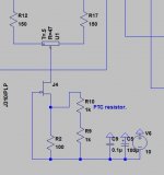
Kees, this is the way I would do it.
I like to use TO-126 devices in thermal feedback as they are easy to place on a heatsink.
Make around 1-2mA through Q2 and as much as you need through Q1.
The higher the temperature of Q2 -> the lower the current through Q1 = the lower the bias.
Cheers,
Valery
P.S. Correct the resistors' values according to the currents you require.
Attachments

Kees, this is the way I would do it.
I like to use TO-126 devices in thermal feedback as they are easy to place on a heatsink.
Make around 1-2mA through Q2 and as much as you need through Q1.
The higher the temperature of Q2 -> the lower the current through Q1 = the lower the bias.
Cheers,
Valery
P.S. Correct the resistors' values according to the currents you require.
Thank you!! this is a very nice schematic, I go try this, I put the mje350 not on the heatsink but on the mosfet because these run very fast due to very low on resistance, when put it on the heatsink itselfs will slowdown to much.
I have also think about a ntc resistor on the CCS resistor in series with another resistor to tune it, also then it will track and also get in count the whole amp temp changes.
A opamp in the circlotron itselfs can be used as a current tracker by measure the current over a source resistor, this way the amp can never again get in trouble, such a current servo can be included with two opams.
regards
Attachments
Last edited:
Kees, this is the way I would do it.
I like to use TO-126 devices in thermal feedback as they are easy to place on a heatsink.
Make around 1-2mA through Q2 and as much as you need through Q1.
The higher the temperature of Q2 -> the lower the current through Q1 = the lower the bias.
Cheers,
Valery
P.S. Correct the resistors' values according to the currents you require.
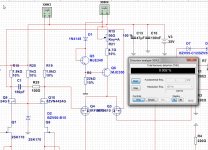
Correct, I do need to use very low resistors to get enough current, however it act as a temp corrected CCS with high
output impedance, maybe a npn can better be used it current transistor?, or do then the vbe do not work?.
It eat some volts, but in mine opinion this driver needs more voltage.
regards
regards
Attachments
Last edited:
Correct, I do need to use very low resistors to get enough current, however it act as a temp corrected CCS with high
output impedance, maybe a npn can better be used it current transistor?, or do then the vbe do not work?.
It eat some volts, but in mine opinion this driver needs more voltage.
regards
regards
Right - you need more voltage headroom to make it working - you may want to increase R18, R19 to move the 2-nd LTP's sources away from the positive rail.
You need to allow at least a few volts Vcb for Q6.
Right - you need more voltage headroom to make it working - you may want to increase R18, R19 to move the 2-nd LTP's sources away from the positive rail.
You need to allow at least a few volts Vcb for Q6.
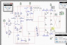
I have changed the CCS of the ltp, to prevent a to low idle current who can spoil the correct driving of the miller irf9610 vas.
Lowering also the R18 and R19 correct then to the right levels.
I go try this and see if it is not overcompensated, adjust this need experiments.
Now the amp is not a allfet anymore, but I still see it as a allfet because we use the bjt outside the audio pad as a temp compensator mosfets here is a little difficult but I go look at it.
regards
Attachments
- Home
- Amplifiers
- Solid State
- allFET circlotron