vzaichenko
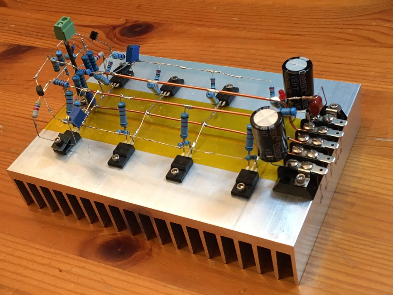
Here is that alexander like amp I did in past, it has 0.001 distortion on 1.3 watts, idle is 60 mA with the ring emmittors who are extremely liniair for a bjt I had the 2sc3264 and the 2sa1295 in this design, and as you see with the diamond input it did wel, original here is a opamp used, I did also use super emittor follower to drive output.
These transistors are so good that set them on 1 amp did not really make more impression on the HD, mosfets however special the irf240 and the capacitances are a real problem get things right, therfore I have now updat the driver so it can some big Cj out to deal with charge/discharge.
regards
Attachments
Hi Kees,
The comparison is not really fair, -60db at 1.3A is not a problem of class AB - it's a problem of particular design.
I can show you a live measurement, taken at 50W @8 ohm, 1KHz - class AB output stage (see attached, -106db). 3 pairs of output devices at 65mA each. Here is more info: Modular NS-OPS
I designed class A amps in the past, but even though I prefer un-compromised quality, I choose a well-designed class AB because of many reasons - including energy efficiency, reliability and maximum output power available.
I mean - you've got a cool design, it's interesting to follow the thread, but it would not be fair to state that class AB is somewhere below class A in terms of sound quality 😉
Cheers,
Valery
These are very nice low HD specs, however seen as audio quality it is maybe so we get a very clinic sounding amp when distortion is such of low level, I have ones build a amp from elektor who was high end and even lower in distortion but it sounded not very well to my ears.
I have another circlotron and I go see later how that sound, it has only degeneration resistors and no feedback, (not whole true because it is also feedback but local.).
What kind of software you have for measurements? looks very cool
Last edited:
X and Banad
I have measure the amp in arta, it is low in HD, however the second is higher, this is because I can not measure the whole bridge because it give a short through the pc,
need a balancen input for that or a transformer or such, but my audio on pc who is a standard chip on mother board give a lot of garbage, I have a audiocard from tascam usb maybe these are better.
tomorrow some listening.
PS the mosfets are strong, I did forgot the fan and the heatsuink get hot, idle was 2.3 amps I did smell something and discover that the amp was on, water on the heatsink did bowl it right away, ssssstttt did I hear.
But nothing broken, this amp is quite strong special that irf240. I need still a solution for run away, but that is the last difficult job.
The measurement was with 5 watts of power.
regards
Attachments
Please post final schematic and board part placement guide - if this is the final fix.
If you ran at 2.3a without fan I would say your thermal runaway problem is controlled.
If you ran at 2.3a without fan I would say your thermal runaway problem is controlled.
Please post final schematic and board part placement guide - if this is the final fix.
If you ran at 2.3a without fan I would say your thermal runaway problem is controlled.
no it is not controlled, the supply did limit otherwise amp was baked, he was I think such a 130 degree warm, I did smell something and that was the amp.
I amp very far with it and post tomorrow the changes and see what happens when I use a bigger heatsink.
regards
Kees
you have PM
regards
No pm seen, but have clean the box, maybe icl yours.
X I did yesterday put feedback to include irf240 however the amp blow, because of a severy oscillation, when I do not include irf and so connect to drains irfp9610/610 it is oke.
Maybe fets are damaged because she are hot, and one time I did forget to tighen screw and smoke came from one of them, but did keep work after.
The oscillation do blow the CCS on ltp because there it is feedback and a clipping 70 volts on 1,2 Mhz do damage.
Maybe the driver section has to much feedback through supplys, I did use 10 ohms need to switch back to last setup with lower idle current, so first replace the irf240.
regards
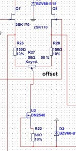
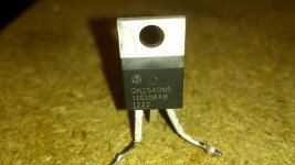
Well amp is on line again, cause are the DN2540 mosfets who blow continously, even she do just 22 mA from a 12 volt source, the mosfets are genuin because came from mouser, but all do blow themselfs in the CCS of the LTP.
I did use the big ones, the oscillation was in fact the smps of the sinus generator who did give some volts of hf, replaced with a normal transformer now.
CCS in picture blow why, because it is just some mA for LTP in fact 2 x 8 mA.
I have search for a calculator so I can calculate the power needed for driver the mosfet, that is in fact not as high as I tought, so can lower the driver idle to 40 mA each with keeping the the bandwidth, give pretty low distortion and so I go do it.
regards
Attachments

Last edited:
If those MOSFETs are dying at 22mA there's something wrong with them or you may have oscillation. Does it make any smoke or sounds before it blows up? My IRFP240's made a characteristics sizzle before dying from thermal runaway. They would literally ooze solder out of their joints between the metal tab and epoxy body. How is the amp sounding now?
Btw, I just made an F5 class A amp that uses just a pair of 2SK170 and 2SJ74 to drive four pairs of 2SJ313 and 2SK2013 MOSFETs to full output with total bias 1.6amps (400mA ea) and probably 25w max. All four MOSFETs had 220R gate stoppers running from a single bus driven by little JFET.
Design is by Juma. I am usin 4 pairs vs 3 show. In schematic.
Last edited:
If those MOSFETs are dying at 22mA there's something wrong with them or you may have oscillation. Does it make any smoke or sounds before it blows up? My IRFP240's made a characteristics sizzle before dying from thermal runaway. They would literally ooze solder out of their joints between the metal tab and epoxy body. How is the amp sounding now?
Btw, I just made an F5 class A amp that uses just a pair of 2SK170 and 2SJ74 to drive four pairs of 2SJ313 and 2SK2013 MOSFETs to full output with total bias 1.6amps (400mA ea) and probably 25w max. All four MOSFETs had 220R gate stoppers running from a single bus driven by little JFET.
Design is by Juma. I am usin 4 pairs vs 3 show. In schematic.
Nice schematic.
The Jfets do driver such much fets?, to see what happens you need to square it and look at a scope what it does.
The feedback resistors can be changed to higher values, 100 ohm 47 ohm and 100 ohm 1k of such, because now it dissipate a lot.
The dn2540 mosfets also the bigger ones do die when using here, the J113 do not, I have these now in the amp, however the irf are died, forgot to tight
the bolds and overheat, sometimes I forget things, to much busy I think and need some days rust, continu thinking do get me tired.
Strange not that J113 stays oke and the db2540 died, I have however seen thet ccs with them has a 1k resistor in the gate.
regards
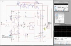
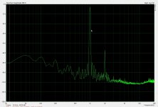
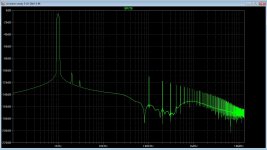
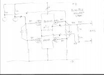
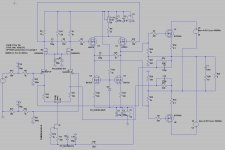
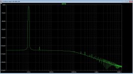
I have change the input fets to J113, the more stronger ones who are also in CCS, th changes is HD are enormous, this is output 12 volts in 8 ohms.
Reason I do also now, the capacitance and miller of the irf9610 needs to be overruled with enough current so onon liniarity do not occur, I think even the BSP49 or PN4392 or 91 because these can easely idling on 10/15 mA who is plenty for driving the irf.
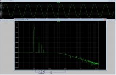
as I now see it is quite low HD until 100Khz it is clean where low pass filter gets in.
thirth -118dB = 0.0001259
second -100 dB = 0.001
All other higher up not measurable as LTspice let see.
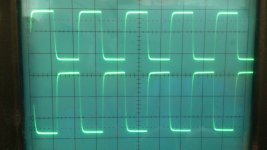
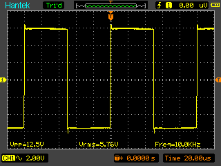
second photo is 20 Khz squares from scope, do not mind the different amplitude, that is a faulty probe (yes also Chinese).
Reason I do also now, the capacitance and miller of the irf9610 needs to be overruled with enough current so onon liniarity do not occur, I think even the BSP49 or PN4392 or 91 because these can easely idling on 10/15 mA who is plenty for driving the irf.
as I now see it is quite low HD until 100Khz it is clean where low pass filter gets in.
thirth -118dB = 0.0001259
second -100 dB = 0.001
All other higher up not measurable as LTspice let see.
second photo is 20 Khz squares from scope, do not mind the different amplitude, that is a faulty probe (yes also Chinese).
Attachments
Last edited:
Nice schematic.
The Jfets do driver such much fets?, to see what happens you need to square it and look at a scope what it does.
The feedback resistors can be changed to higher values, 100 ohm 47 ohm and 100 ohm 1k of such, because now it dissipate a lot.
The dn2540 mosfets also the bigger ones do die when using here, the J113 do not, I have these now in the amp, however the irf are died, forgot to tight
the bolds and overheat, sometimes I forget things, to much busy I think and need some days rust, continu thinking do get me tired.
Strange not that J113 stays oke and the db2540 died, I have however seen thet ccs with them has a 1k resistor in the gate.
regards
I don't have an oscope but Juma's design has been pretty much well tested so I think it's good. It certainly sounds very nice - one of my best class A thus far. I hear no distortion and don't pick up any excessive distortion in speaker distortion test. Better than the M2 which does have audible and measurable distortion at the speaker.
These are also just inexpensive MOSFETs from China - who knows if real but sound nice. $4.77 for 5 pairs.
From Juma's thread adding 1nF across 100ohm resistors will help overshoot. I changed feedback from 2 00T in parallel to one 100R for 20dB gain. Sounds better as 20DB. I don't know why all Pass amps are designed around 14dB gain vs usual 26dB that everyone else uses.
I will try adding 680pF film caps across the 100R later. I don't hear any grain or sinbillance though as is. It's a fast amp that's for sure.
Last edited:
Agree!
it is very nice results for sure !
btw , hope that this A-class PP drivers common sources configuration can improve amp THD factor even slightly more .🙂
Banat
This is a nice schematic and I go try this in simulation to see if it do a better job, as I see now the 2sk170 jfet do not good with current feedback and is a cause, I think we need a jfet who can stand more mA because of the feedback wo also put some extra mA.
thanks for al the support X and Banat.
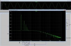
X the measurement is on output.
here some more, with first picture the LTP and the VAS.
Last picture switch back to the 2sk170 giving mucho worse result, possible because this fet is to weak in mA.
Banat, when use a SE with a double CCS load it can also work is I do use enough idle current it it, a CCS loaded driver is more liniair also, it follows the signal nicely in tube world we make a lot use of it, your schematic is very nice and is also a drain follower however it has a driven lower half, makes impedance lower and as such more drive capability, I have zeners there so no signal feedback, I go for shure test your idea.
regards
Attachments

Last edited:
I don't have an oscope but Juma's design has been pretty much well tested so I think it's good. It certainly sounds very nice - one of my best class A thus far. I hear no distortion and don't pick up any excessive distortion in speaker distortion test. Better than the M2 which does have audible and measurable distortion at the speaker.
These are also just inexpensive MOSFETs from China - who knows if real but sound nice. $4.77 for 5 pairs.
From Juma's thread adding 1nF across 100ohm resistors will help overshoot. I changed feedback from 2 00T in parallel to one 100R for 20dB gain. Sounds better as 20DB. I don't know why all Pass amps are designed around 14dB gain vs usual 26dB that everyone else uses.
I will try adding 680pF film caps across the 100R later. I don't hear any grain or sinbillance though as is. It's a fast amp that's for sure.
try measure a 100Khz square, gor the 20 dB, the best way to go from experience is 30 dB, but maybe you get then more distortion because of low open loop, maybe test the distortion is a way to test more things abotut the amp, driving a big mosfet 2.2nF with a 2sk170 seems for me so difficult to believe, as the power mosfets are source followers the signal follows excaclty the 2sk170 output voltage and capacitance is of less care, no miller and such, that is why I did lower the idle of the driver SE to 30 mA with much better results, but a drain follower with a irfp240 will give asit is amplify 3 times is 3 x 2.2nF gate capacitance, that is why in mine amp the irf9610 do load the ltp and as such need jfets who have bigger balls.
O yes when you use a BSP149 or the DN2540 in your schematic to drive the
mosfets you maybe supprised, these have a lot more balls.
regards
Agree!
it is very nice results for sure !
btw , hope that this A-class PP drivers common sources configuration can improve amp THD factor even slightly more .🙂
This does load the LTP to much, a ccs loaded pair has lower capacitances, idle the enough will down HD to 0.001.
Thanks for the ideas.
regards
Kees
It is not surprise that PP A-class drivers load to much the LTP input stage ,
question , did exist possibility to put even more powerfull FET devices on the top of LTP cascode to improve driving capability ? ,
since I believe that suggested PP-A class drivers can effortless to drive the gates of OPS .
regards
Last edited:
the irf9610 has some amps capabillity, so these can do it effortless , I can even use fets who have lower current because for the ops we need some 1 amp or so peaks.
i have now make changes permanent and it has very low distortion now, however when I try to put a cap in feedback in real amp oscillate dramatic, now I have make the idle current of the drivers half as it was, it do much better, so I go try now again the caps, we need them for overshoot purposes.
using other Jfets in input like the PN94392 or better the J113 do make the distortion mucho lower strangely, I think because of current feedback a Jfet with higher current capability is cause of better respons, we feed current back to them as current feedback, the CCS keeps things stable as otherwise that feedback do not work properly a resistor there as we did first do not work because is a constant voltage..
regards
Attachments
- Home
- Amplifiers
- Solid State
- allFET circlotron