The wait is over. Order of IRF610 and IRF9610's and 2J113's came in from Digikey today. I can start stuffing boards. Now just need to find the right stuffing guide. The PSU for this amp is a bit of a pain. I think that is probably the biggest drawback with a floating power supply design like a Circlotron is the sheer number of independent isolated PSU's.
You can do it, I believe in you! 😀
You can have a custom made transformer with four secondary from SumR.
Ciao!
Do
You can have a custom made transformer with four secondary from SumR.
Ciao!
Do
X
Yes that is what I mean, just do destignator of components as use for build up in stages. like R1 R2 etc.
Have a cleaned up schematic and board for clarity
regards
Do I have to have a PTCSOD70 temperature compensator in place? Can it be jumpered with a wire to start things off? Also, I don't have a 47R or 100R pot. My lowest value pot is 500R. Can I use that?
I am going to put a 2k resistor across the "Experimental" part for now to make sure there is a completed tempco circuit.
Last edited:
I am not sure what to do about the Feedback pins SV1 and SV2? Are pins supposed to be jumpered?
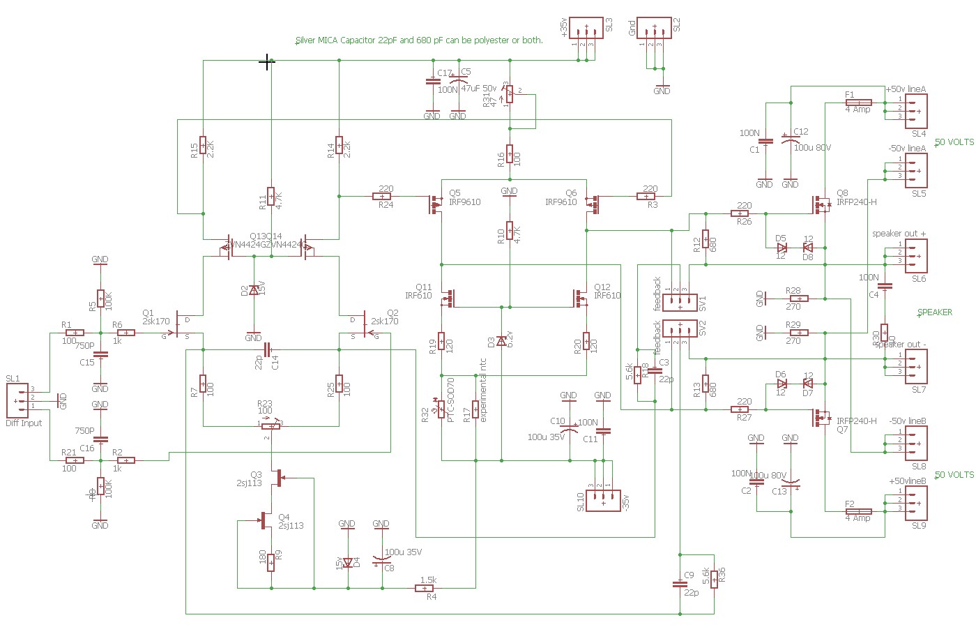
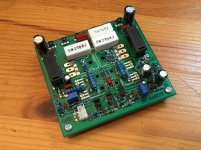
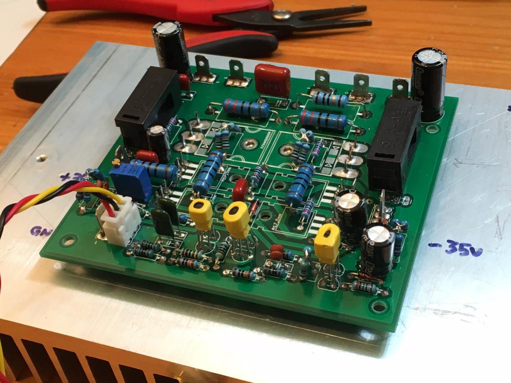
Here is the allFET Circloton before the power MOSFETs are installed. Kees suggested testing each stage first before installing power MOSFETs. Stage 1 consists of the 2SK170's, 2SJ113's and ZVX4424G's. Their output is the Gate pins of the IRF610 and IRF9610. If those are pegged to the rails, then something is wrong and needs debugging before moving on to the next stage (by soldering in MOSFETs).
I had to improvise some of the values for the resistors to get the higher wattage ratings (parallel or series parallel were used). I think I have to get the proper value pots or this will not work. Need 100R and 47R trimpots. Should have ordered those but did not realize they were such low values.
Attachments
Last edited:
I am not sure what to do about the Feedback pins SV1 and SV2? Are pins supposed to be jumpered?
Here is the allFET Circloton before the power MOSFETs are installed. Kees suggested testing each stage first before installing power MOSFETs. Stage 1 consists of the 2SK170's, 2SJ113's and ZVX4424G's. Their output is the Gate pins of the IRF610 and IRF9610. If those are pegged to the rails, then something is wrong and needs debugging before moving on to the next stage (by soldering in MOSFETs).
I had to improvise some of the values for the resistors to get the higher wattage ratings (parallel or series parallel were used). I think I have to get the proper value pots or this will not work. Need 100R and 47R trimpots. Should have ordered those but did not realize they were such low values.
X
A more complicated psu is always a drawback of a circlotron, and as sims says 500 mA can be plenty for the pre-amp, as long there are no more then 4 power mosfets to drive.
and a supply who is independent windings, x 2 the preamp supply one is enough, and 500 mA for two can be tryed, I have a dc coupled tube/mosfet amp who has a transformer of 100 mA and do well (two power mosfets)
500mA is quite more easy.
The adjustable resistors, (pot) you need for the differential 50 ohms, not higher, it destroy adjustment of the part and offset do not work, for the current you can put a 500 ohm in but adjustment get tricky, however for testing it do work, the 50 ohm pot in differential can be temperary two 47 ohm resistors so you can test.
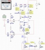
Als control the pinout of all the mosfets, I have done that in eagle, but I am uman and these anymals make mistakes sometimes, through schematic you can control that.
Please put irf610 and 9610 on a heatsink before attemt to test, she draw enough current to get hot, the resistors who are 120 ohm or 100 ohm draw current, the pot also, a 500 ohm pot is in series so setup max resistance can bring things in a safe area, and so testing can be done.
The feedback loops are jumpers, like in a motherboard or hd. here you can choose if the powermosfets are also part of loop or only the preamp output, getting possible tube like sound, but we now for shure when ready and measuring harmonics.
My brother has cancer and go to die, so I am busy supporting them, but between that I do assemble the board also, now waiting for some parts.
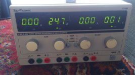
I use the lab supply as seen ik pc three, but this has max 30 volts, so I have to work with that for now, 5 volts more do not so much I hope.
regards
regards
Attachments
Last edited:
Thanks for the tips Kees. I am so sorry to hear of your brother's cancer - please take time to do what you need as this is hobby after all. Thanks for all your work to get me to this point. It is quite exciting and as this amp is a completely different animal than any other amp I have built, it is interesting, and at the same time challenging as I have no idea how to set it up. 🙂
Regards,
X
p.s., I have a new 25VAC center tap 10VA toroidal trafo (I should have bought bigger one) that I was going to use to power the input stage for 35v rails. Will that be enough current? I think circa 280mA is what it's rated for at 35v (although Antek says their trafos can be safely pushed above rating a bit without problems).
Last edited:
It seems small ! Do you have photo of the other side ???
Other side not populated with power MOSFETs yet as we install them step by step after I confirm the input stage is working well by checking the gate voltages of the VAS stage (IRF610/9610). Once that is good then install the 610/9610's and check gate voltages of the outputs prior to install.
Yes, it is a very compact amp - a great job Kees did to layout something this complex in such a footprint. My request was that it fit within 100mm x 100mm for cost effective PCB's. It is smaller than that.
Have you ever seen such a small amp have 9 spade connectors? 🙂
Thanks for the tips Kees. I am so sorry to hear of your brother's cancer - please take time to do what you need as this is hobby after all. Thanks for all your work to get me to this point. It is quite exciting and as this amp is a completely different animal than any other amp I have built, it is interesting, and at the same time challenging as I have no idea how to set it up. 🙂
Regards,
X
p.s., I have a new 25VAC center tap 10VA toroidal trafo (I should have bought bigger one) that I was going to use to power the input stage for 35v rails. Will that be enough current? I think circa 280mA is what it's rated for at 35v (although Antek says their trafos can be safely pushed above rating a bit without problems).
X thanks for the kudo's as she are called, a time ago. my
Brother has already a depression for years and did want to die for a long time, now it that far and hope things get without suffering, soon he may sleep on the bed of God and in the meanwhile his soul go search for a new home, as for all of uss will happen.
Oke no religion because I am a atheist, for the supply, 280mA can be enough for one preamp, I do not now if it is strong enough for two, but you can play with it, as I say control also pinout of the transistors, I think it is oke but I can still make mistakes.
Putting on such a smal pcb is a challence for a circlotron, things are flipped or how you call that.
regards

LOL. I had a 100uF elco blow up like a firecracker the other day - first time I ever soldered one in backwards. 🙂
Luckily nothing damaged and no one hurt.
One has to be respectful of the tremendous power stored in a 400VA toroidal trafo powering a class A amp.
Luckily nothing damaged and no one hurt.
One has to be respectful of the tremendous power stored in a 400VA toroidal trafo powering a class A amp.
LOL. I had a 100uF elco blow up like a firecracker the other day - first time I ever soldered one in backwards. 🙂
Luckily nothing damaged and no one hurt.
One has to be respectful of the tremendous power stored in a 400VA toroidal trafo powering a class A amp.
You need to be respectfull for all electronics, did blow up a board who has only 5 volts and 100 ma, very expensive welding driver board,.
Swedish invention do double the solar cel output was on news here, these are the things we want for our children future.
Per your suggestion got rid of wire wound cement resistors to avoid inductances. Using lower 2w 220R vs 270R.
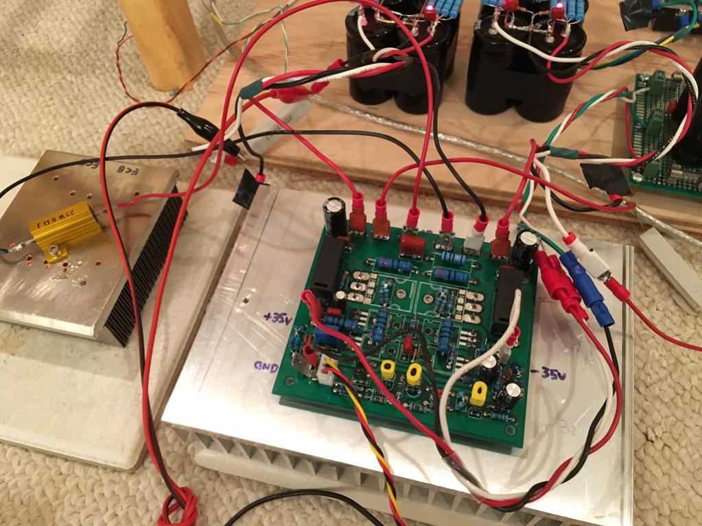
Installed IRF610/9610. Tested and voltages behaving with 35v rails on input stage. Looks good. Mounting on heatsink is tricky to get screws and insulator washers underneath board. Very secure once screwed down though. Won't need corner standoffs.
Installed IRF610/9610. Tested and voltages behaving with 35v rails on input stage. Looks good. Mounting on heatsink is tricky to get screws and insulator washers underneath board. Very secure once screwed down though. Won't need corner standoffs.
Here is a closeup of the allFET as mounted on a heatsink.
Testing the amp with 35v rails on the input stage and 25v dual supplies on the output stage. I got the bias control to work for a while and now, no bias happening anymore. I am using a 25w 8R power resistor as the "speaker". This is not easy...
Testing the amp with 35v rails on the input stage and 25v dual supplies on the output stage. I got the bias control to work for a while and now, no bias happening anymore. I am using a 25w 8R power resistor as the "speaker". This is not easy...
Attachments


Here is a closeup of the allFET as mounted on a heatsink.
Testing the amp with 35v rails on the input stage and 25v dual supplies on the output stage. I got the bias control to work for a while and now, no bias happening anymore. I am using a 25w 8R power resistor as the "speaker". This is not easy...
It is possible the pot who do arrrange the bias is broken, because a 500 ohm pot is just 0.25 watt that is why you need 50 ohm, it is much easyer to manage, first with th 180 ohm resistor in the cascoded currentsource j113 adjust that so the zvn 4424 draw 5 mA each what will happen automatically.
And X if things are easy, live looses the challence. first do the driver working, then put output transistors in, before you blow things..
measure over the 2.2k R11 10.5 11 volts is needed then you can put in the correspondencing resistor forR9 now 180 ohm.
Maybe your ballast resistor is burnd out, you can test offset and current also with a higher resistor and offset even without.
measure then also the 120 ohm resistors on both sides of irf610/9610 fase inverter, R19 and R20. I did sims here 55 mA, giving the irf 800 mW dissipation, lower current source soms more.
If here the pot do not respons anymore, possible a fet failure or pot burnt, just measure over the 120 ohm resistors, it need there 2.1 volts for 55mA, it changes when turn pot, what you did with the PTC, maybe when warm it shuts off idle completely, just put in a 10 ohm resistor of such it is for later care, the j113 has not need to bind together, because these current source do not drift.
Glad that we get slowly there, here we have a indian summer, coming days above 30 oC for september it will blow highest temp measured in all time.s and so I enjoy because we had a very wet summer.
Did are the pinouts were all oke? put in transtistors as in the print is oke? you did not tell.
I can in sim adjust the idle pot between 48 and 60 mA, resulting in 300 mA to 29 A in output, so when wrong, things blow, in your case the safety resistors you need to use.
And X the zeners on the power transistor gates who are smt are not mounted why?, it is saver to di this special in a design fase.
regards
Last edited:
The pinouts look ok - I checked all against published drawings. I did not mount zeners on mosfet because you do not have it in drawing and it is not labeled on the stuffing diagram you made. I thought it was another "option" for future use like the PTC and Feedback jumpers. If a part is critical, you need to show it on stuffing diagram as boards is absent all component labels.
I suppose the pot may be burned out - did not check it but it does seem to change the amplitude of distorted output. Current only flows when input has signal otherwise no bias.
I have big mosfets in already and they have not blow up yet.
I suppose the pot may be burned out - did not check it but it does seem to change the amplitude of distorted output. Current only flows when input has signal otherwise no bias.
I have big mosfets in already and they have not blow up yet.
Maybe you blow the irf or a pot, 500 ohms pot is just 0.25 w.
I go try mine tomorrow, after that it get trocial here, and go enjoy that last indian
summer before winter for energy.
The fact it did work first make a transistor suspect
For the zeners you need to use the types I do have sim, 15 volts and 6,8 volts, 5,1 volts
is to low, you get idle problems because fet do not open, use 6.8 volts here. special for the
input stage the zeners do give the proper voltages, 15 or 18 volts here is not such a problem
but in driver stage it is, idle differences and such.
34 volts over the 2.2 k resistor is way to high, this means there is no room left for swing,
because of the current is much to high, 180 ohm resistor change is needed for to get the proper
voltages otherwise things blow. chenk the 2sk170 and zvn4424 or these are still oke, because
she draw 10 mA each that is twice as much and left no more room for swing.
distortion come because here is much to much current through jfet input, or top irf are blown
getting 35 volts through the gates and to the 2.2k resistor.
For the gate protection diode, you have to now yourselfs these are needed, maube not here but it is save, the fact that the print on the pcb was not oke, the smt zeners are so small print is not there but is point out to itselfs, for me if I see this I now why she there, but have afcouse some experience in amp design trial and error.
sleep wel.
kees
Last edited:
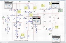
I did discover in sim that the cascoded jfet current source is the wrong jfet, because the j113 do not well, i get to little current through the input fets, and this is the cause that voltage drop over R15 and R14 is mucho to low, in your case X it sit almost on rail level, 35 v supply and 34 volts is just one volt, and then you have no audio or as you say sometimes peaks.
we need a cascoded current source or maybe even a current source like j511, but do not now if these have high impedance because we need this there.
I have tryed some j fets in current source only j 310 work, mayeb there are more but I go seek.
regards
we need a cascoded current source or maybe even a current source like j511, but do not now if these have high impedance because we need this there.
I have tryed some j fets in current source only j 310 work, mayeb there are more but I go seek.
regards
I'm going to have to order all the parts I am missing like correct value pots. What wattage rating does the 100R and 50R pot need to be? Also need the exact Zener diode values. I think I can snip the leads off a 12v axial Zener and use it on the SMT pads.
Maybe a way to improvise a CCS with a BJT and LED in that position? Like BC546 to get things going? I am not going to complain if using a BJT means getting sound out of it vs nothing.
Who did sim not show problem earlier - because you did not check current?
Who did sim not show problem earlier - because you did not check current?
- Home
- Amplifiers
- Solid State
- allFET circlotron