Have you compared ccs filament supply vs LCL?
Ah - I see you have been looking at Thomas Mayer's filament supplies - he uses LCL. No I haven't tried that. Could be good.
Andy is using my RC-V9 regulator, so it's OK - there is no output capacitor connected to the regulators.Then the last cap in PSU is very important.
The regulators are designed to isolate the filament from the Raw DC supply, and any capacitors; and the output impedance is greater than any (realistically practical) size of inductor.
Understood. The last cap in B+ supply is in the AC path in filament bias circuit and its effect is audible - hence my comment above. DC linked MKP caps are not bad and not too large - definitely a practical solution if there is no space for PIO or foil caps.Andy is using my RC-V9 regulator, so it's OK - there is no output capacitor connected to the regulators.
The regulators are designed to isolate the filament from the Raw DC supply, and any capacitors; and the output impedance is greater than any (realistically practical) size of inductor.
B+ (final capacitor) effect is the same for all bias methods, though...
For B+ capacitor, careful check on the datasheets for DC-Link capacitors shows a lot of variation.
I am working with 500V Panasonic EZP; it shows <6mΩ ESR (10kHz, typ.) which makes them electrically very close to foil variants, and much improved on ordinary MKPs. Maybe foil gives electromechanical improvements - I have not measured that yet.
Ultrapath or parafeed would reduce the PSU cap influence. The problem of finding a nice sounding cap remains in any case. Thanks for sharing your experience of Panasonic EZP.B+ (final capacitor) effect is the same for all bias methods, though...
For B+ capacitor, careful check on the datasheets for DC-Link capacitors shows a lot of variation.
I am working with 500V Panasonic EZP; it shows <6mΩ ESR (10kHz, typ.) which makes them electrically very close to foil variants, and much improved on ordinary MKPs. Maybe foil gives electromechanical improvements - I have not measured that yet.
I've been consulting this 2022 thread on film and foil caps - pretty hard to find. Post any info if you know of sources.
https://www.diyaudio.com/community/...itor-manufacturers-not-boutique.390675/page-2
https://www.diyaudio.com/community/...itor-manufacturers-not-boutique.390675/page-2
For large values, 4 uF and up, I look for old solder-sealed capacitors in metal cases. One sure sign of foil capacitor is the word "condenser". When they called them condensers, metallization was not yet invented.Post any info if you know of sources.
Size of capacitor matters. If it looks too small for its capacitance and voltage, it is likely metallized
Russian KBG capacitors are true foil paper-in-oil. K40Y also, but those come only in small values. All Russian capacitors that have "MB" in their name are metallized paper.
Foil capacitors have low ESR, but they are more inductive than DC links.
Last edited:
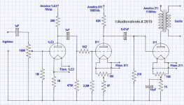
Here's my present amp with 112A input tube. I managed to find some old metal case PIO caps in my cupboards and put one in first position in the PSU and it did indeed make a difference. Sounds very nice.

It's being rebuilt at the moment. Plus I have separate power and filament supplies for the 2a3 output stage and for the 112A input stage. It's something I'm working on right now. So later I could post something. The filaments are CLC. The B+ is basically CLCRC with a PIO cap as first cap followed by DC Link caps. I have a 5U4 for the 2a3 stage and solid state 1200V SIC diodes for the input stage.Could we see your power supply schematic?
Thanks for the schematic, Andy. I'm unfamiliar with input transformers so I've got a basic wiring question.Here's my present amp with 112A input tube. I managed to find some old metal case PIO caps in my cupboards and put one in first position in the PSU and it did indeed make a difference. Sounds very nice.
View attachment 1097984
The Hammonds have a single 36k primary and two 550 ohm secondaries. If you're running them as 1:4 step up transformers, does that mean the input side consists of the two 550 ohm "secondaries" in series and the 36k "primary" connects to the input/driver tube?
They also have some shield connections, how do you have those wired?
I connected the violet wires to the chassis earth and the grey/grey-white to the signal ground, together with brown and red-yellow. The 550R windings are indeed in series, so red connected to green-yellow. Input positive on green and output positive on orange. I recommend these as step-ups. Quite a bargain, and then you can play around with DHT inputs.

Can be wired 1:4 as autotransformer, or 1:3 as transformer.Can a UTC A20 be wired similarly as 1:4?
Newby here. Would someone help me understand all the different ratios that can be obtained using my UTC A-20 as well as how to wire it as an autotransformer? Just to get me started experimenting for myself along the lines of what Andy is learning here.

Most ratios are given in the table in your data sheet.Newby here. Would someone help me understand all the different ratios that can be obtained using my UTC A-20 as well as how to wire it as an autotransformer? Just to get me started experimenting for myself along the lines of what Andy is learning here.
View attachment 1098576
A20 has four center-tapped 150 Ohm windings. Each of them can be used as part of primary or secondary.
1:1 connection (600:600) is straightforward, two windings in series on one side, and two other windings in series on the other side.
1:2 connection (150:600) - two windings in parallel, two other windings in series.
1:3 connection (150:1.35K), one winding as primary, three others in series.
Autoformer: (2.4K) all windings in series.
- Home
- Amplifiers
- Tubes / Valves
- All-DHT amplifiers: no indirectly heated signal tubes!