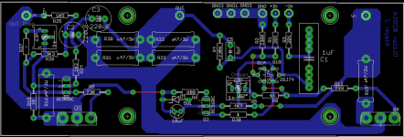
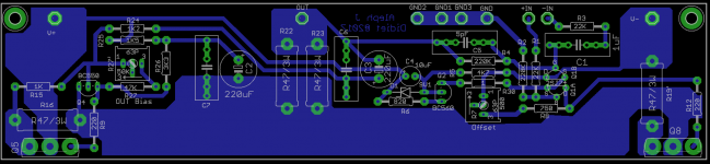
I found one small error. Get rid of R22 and R23.Yes..
i am not able to make much more today, as i have got to prepare for newyears eve now


Papa generally goes with 2 to 1 ratio. Total effective resistance of R20 R21, R22, and R23 should be half the value of R16. So get rid of R22 and R23 ie total resistance in that area should be 0.47/2.

Update, waiting new values 😀 it comply with UMS, diyaudio heatsink
R7 should probably be around 750 Ohms with 500 Ohm trim pot.
You could also do something like R7 = 2k with 5k trimpot in parallel.
It will depend on the desired bias point of the amp.
R7 say 680R-750R plus 500R trimpot
these two in parallel ........ naah
R27 47K, R27' 47K (or 50K )
pcb - rearrange parts around C4 , make that lowest trace fatter
these two in parallel ........ naah
R27 47K, R27' 47K (or 50K )
pcb - rearrange parts around C4 , make that lowest trace fatter
I just need to get didiet interested in my projects.
😀
😀 if not in lazy mode, i can help making layout, just send schematic
Attachments
😀 if not in lazy mode, i can help making layout, just send schematic
Goodmorning all here!
I really appreciate the effort you do (and the rest here too 🙂)
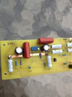
Well, didiet is it possible that you can make some more space for C6,C7.
If you look at the attached picture, (My diy AlephJ pcb) you can see my caramelized capacitor's 😀, they are pretty big (Same size as C1)... So that would be cool. -Also for the possibility to make the pcb by hand, it would be nice if you could post the size of the pcb (When printing it's important ofcause)
Happy new year!
Jesper.
Attachments

you can `skip C1
If i don't want balanced input, we could skip C1 and R3 right ?
Or will it affect some stability ???
🙂
Jesper.
🙂 Didiet, you are very good at this layout... thanks.
But i got two things, that i would really like.
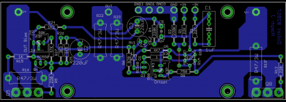
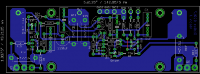
1. If not to much trouble for you, can you do a special non UMS layout where distance from center mosfet q5 to q7 is 170mm; this is because of dissipation/heattransfer in my chassis will be best this way!
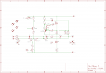
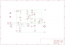
2. Will you post the final schematic also?
Jesper.
But i got two things, that i would really like.
1. If not to much trouble for you, can you do a special non UMS layout where distance from center mosfet q5 to q7 is 170mm; this is because of dissipation/heattransfer in my chassis will be best this way!
2. Will you post the final schematic also?
Jesper.
SE or balanced , you can short C1
take a look at Babelfish J (be it ancient one or recent v.2)
Yes... I allways was wundering, why input was cap-coubled at -IN, and not at +IN ? - Think you did answer that for me now, thanks.
Jesper.
🙂 Didiet, you are very good at this layout... thanks.
But i got two things, that i would really like.
1. If not to much trouble for you, can you do a special non UMS layout where distance from center mosfet q5 to q7 is 170mm; this is because of dissipation/heattransfer in my chassis will be best this way!
2. Will you post the final schematic also?
Jesper.
170mm betwen mosfet. Or 340 betwen mosfet ?
Attachments
- Status
- Not open for further replies.
- Home
- Amplifiers
- Pass Labs
- AlephJ Mimi! (Mini)