most important thing Papa gave us is zillion of puzzles/legos and recipe use your brain and play
Totally agreed.

use 2x15Vac xformer , resulting in 18Vdc rails
set iq to 1A2 or something like that
use one pair of IRFP240
choose pcbs of your liking (any Aleph type) , post here what's your choice and exact schematic for that pcb and I'll wrote what to change for your needs
You are very kind ZM... Thanks.
I allways did like the alephJ; my F5 and this AJ has been in and out of my amp. some times last few years, and really we like the AlephJ most. But amp. is to big 🙂
I have an 15v x 2 transformer (2x5A ~120VA), which could be big enough for testing one channel. When testing is done, and everything is good, the amp will be dual mono in one chassis.
I have attached the AlephJ schm. and the BOM from the DIYaudio store here, but i really would have liked that the values was written on the schematic instead. If you need that, then i can go to my work and print it out, write the values on the schematic, and scan it up again?
Again thank you for helping me ZM (and all others here too)
BTW.: I dont need balanced input, if it makes any difference (maybee schm. will be more simplified
Edit: PCB Will be Diy AS allways
Jesper.
Attachments
Last edited:

will reply later tonight , with edited schm for your needs
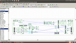
Guess i Will start my diptrace pcb layout now 😎
Jesper...
ZM.
Whenever you got time and place. I was hoping that one output pair would suffice for this mini-AlephJ ?
Good day.
Jesper.
Whenever you got time and place. I was hoping that one output pair would suffice for this mini-AlephJ ?
Good day.
Jesper.
Morning all.
I started a layout for this proto mini alephj tryout 🙂
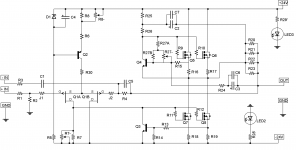
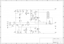
Maybee someone could have a look at attached schematic? -I have removed one pair of output mosfets (IRFP240).
If one look at the connections of the original dual output schematic, there is a connection from transistor q4 to q5 (upper half of circuit) and a connection from q3 to q8 (lower half of circuit)
The connection from q8 i removed and connected it to q7 instead (See attachments)
Is this correct? -Maybee someone could explain? -I mean i don't understand why connection from q3/q4 only goes to one of the output pairs on original AlephJ schm, 😕
Jesper.
I started a layout for this proto mini alephj tryout 🙂
Maybee someone could have a look at attached schematic? -I have removed one pair of output mosfets (IRFP240).
If one look at the connections of the original dual output schematic, there is a connection from transistor q4 to q5 (upper half of circuit) and a connection from q3 to q8 (lower half of circuit)
The connection from q8 i removed and connected it to q7 instead (See attachments)
Is this correct? -Maybee someone could explain? -I mean i don't understand why connection from q3/q4 only goes to one of the output pairs on original AlephJ schm, 😕
Jesper.
Attachments
Referring to Bablefish J (not Aleph J), is Q3 a recent modification?
I don't think I noticed that the last time I checked it (a while ago).
I don't think I noticed that the last time I checked it (a while ago).
Last edited:
-I mean i don't understand why connection from q3/q4 only goes to one of the output pairs on original AlephJ schm, 😕
Jesper.
It controls the voltage at the gate of both mosfets, it does not need to be connected to both mosfet source pins to achieve that.
I would leave off Q3 altogether. It's only there for fools who abuse their equipment.
Last edited:
Thanks...
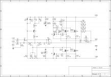
I found the original schm.
There is added an extra pot in diyaudiostore's schm. for adjusting around R27,
I see in original schematic, the connections i was in doubt about, goes excatly like i changed it too 😀
Youre proberly right about q3, but i cant tell!
Jesper.
I found the original schm.
There is added an extra pot in diyaudiostore's schm. for adjusting around R27,
I see in original schematic, the connections i was in doubt about, goes excatly like i changed it too 😀
Youre proberly right about q3, but i cant tell!
Jesper.
Attachments
You're modded circuit is perfectly ok (just in case you're still worried).
Thank's... youre explanation cleared it out.
I am doing some layout at moment... still long to go through 🙂
Jesper.
Attachments
as far as I can see , everything is OK
you can excludeQ3,R13,R14 (overcurrent protection)
put trimpot (as variable resistor) +resistor combo instead of R7 and instead of R27
you can excludeQ3,R13,R14 (overcurrent protection)
put trimpot (as variable resistor) +resistor combo instead of R7 and instead of R27
as far as I can see , everything is OK
put trimpot (as variable resistor) +resistor combo instead of R7 and instead of R27
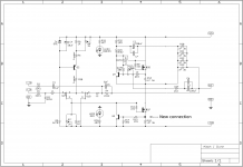
I did, it's also in diyaudio store schematic.
I attached the schematic i use for reference.
About removing Q3,R13,R14 (overcurrent protection), i will post later
Thanks both of you!
Jesper.
Attachments
looking at that schematic :
- remove R8'
-remove R27B, use R27 and R27A
-put R7 and R7' in series in drain
will tell you exact values later , still on first morning coffee
- remove R8'
-remove R27B, use R27 and R27A
-put R7 and R7' in series in drain
will tell you exact values later , still on first morning coffee
leave it as per Papa's schematic
he's having damn good reason for these values
Yeah exactly, no need for trimpot BS
looking at that schematic :
- remove R8'
-remove R27B, use R27 and R27A
-put R7 and R7' in series in drain
will tell you exact values later , still on first morning coffee
Yes..
I understand.
When you got time to calculate resistors ZM; I will make layout with all the changes we agree along the way. No need to rush; i am not able to make much more today, as i have got to prepare for newyears eve now


- Status
- Not open for further replies.
- Home
- Amplifiers
- Pass Labs
- AlephJ Mimi! (Mini)