Today I wound some chokes so I though it may interest some of you.
I was not happy with the idea of the bar chokes with bigg losses.
Exploring a few options, the issues were losses (heat), ripple reduction and holding the supply rails.
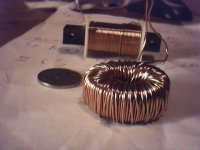
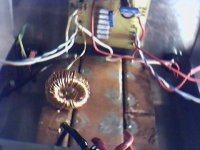
Finally I decided to take a punt a wind some high current chokes using Iron powdered toriodal cores. The ones I used are 39mm in diameter and use a material called Hy-2, they are yellow in appearance and coated with an epoxy finish.
They took about 3/4 hour each to wind, my fingers are sore but the results appear worthwhile.
Heres the tech stuff:
http://www.allegromicro.com/techpub2/arnold/bcore.pdf
My very limited understanding is that while there are many variety of these cores, the idea is that the iron power mix creates a sort of continous air gap, improving performance in a number of areas.
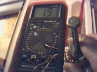
With three layers of 1.00 mm copper wire I got 1.9 Mh for a dcr 85 milliohms , the voltage drop is about 1.17 volts. According to the simulator the ripple is about 62 millivolts...not bad.
I have put a small speaker on the amp and there is only the faintest hum (no inputs), the proximity of the tranformer and high current wiring on the test bench appears to shround the hum the filters rails.
Similar chokes in Farrnels catalogue rated from 5 - 10 amps but not this combination of L and DCR.
Oh, I nearly forgot to mention, the rails are now 25.76 volts, about double the Baby X.
macka
I was not happy with the idea of the bar chokes with bigg losses.
Exploring a few options, the issues were losses (heat), ripple reduction and holding the supply rails.
Finally I decided to take a punt a wind some high current chokes using Iron powdered toriodal cores. The ones I used are 39mm in diameter and use a material called Hy-2, they are yellow in appearance and coated with an epoxy finish.
They took about 3/4 hour each to wind, my fingers are sore but the results appear worthwhile.
Heres the tech stuff:
http://www.allegromicro.com/techpub2/arnold/bcore.pdf
My very limited understanding is that while there are many variety of these cores, the idea is that the iron power mix creates a sort of continous air gap, improving performance in a number of areas.
With three layers of 1.00 mm copper wire I got 1.9 Mh for a dcr 85 milliohms , the voltage drop is about 1.17 volts. According to the simulator the ripple is about 62 millivolts...not bad.
I have put a small speaker on the amp and there is only the faintest hum (no inputs), the proximity of the tranformer and high current wiring on the test bench appears to shround the hum the filters rails.
Similar chokes in Farrnels catalogue rated from 5 - 10 amps but not this combination of L and DCR.
Oh, I nearly forgot to mention, the rails are now 25.76 volts, about double the Baby X.
macka
Good idea,
I suppose you wanna prize Ha!!
I was more concerned about a shorted turn mounting b/n two metal surfaces and metal (steel in the centre), however this may not be the case, only when you short the top of the bolt the other end?
macka
Where do I mail the prize...email me you details ( a free sample........this will jump start the thread)
macka😎
Ps a Bird in the hand is worth two in the bush.
Attachments
Okay,
The picture tells the story.....this is what I like about diy ..and the forum...we can tend to mix up the theory sometimes...but we bounce off each other and work out the solution.
Thanks Taco
macka😉
Ps That 5 1/2 inch bolt is just for illustration, not the one I will be using Okay Guys...its for holding down two meaty power toroidals
Attachments
There are obviously some constraints on space etc when fitting evething to an existing box but I thing the payoff with be worthwhile.
The plan is to jig everthing up and try to test for any unforseen problems before I put all the bolts in and the lid on.
I hope to use the Aleph regular driver boards for a mini Aleph integrated amp or a biamp system with an active Passover??? or maybe an Aleph 60 which is a lot more economic than a pair of Aleph 2's....I still like the Aleph sound.
macka🙄
Attachments
Macka,
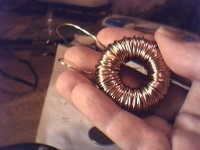
is that laquered magnet wire you are using or uninsulated wire?
It looks like the latter from the pics.
is that laquered magnet wire you are using or uninsulated wire?
It looks like the latter from the pics.
Sorry Grataku,
My lighting and over exposure does not portray this well.
The picture is post 222 is clear.
The reel states it is in fact 1.00 mm enamel copper wire for winding chokes, crossover coils etc.
I have never heard of laquor coated copper and I have searched the calatoge , they do not sell it?
macka
My lighting and over exposure does not portray this well.
The picture is post 222 is clear.
The reel states it is in fact 1.00 mm enamel copper wire for winding chokes, crossover coils etc.
I have never heard of laquor coated copper and I have searched the calatoge , they do not sell it?
macka
This bunch of posts should be titled Retro Fitting The X Aleph to the Aleph but who cares, I just think everyone should be aware it's not that hard.
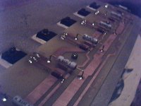
One of my 1st considerations was to determine if the exisiting matched fet sets for the Aleph 2 (2) x (6) , tested at 0.5 amp each, would still be a match for 1.00 amps for my design.
So with my trusty 22 volt lab supply (actually an unused 15 watt JLH supply regulator...(Mr Pass will growl at Me)) I carefully tested all the fets. To do this I made a jig so that I would not have to remove each fet from the exiting heat sink.
This entailed lifting one end of each of the 1.00 ohm source resisters from the board and carefully shorting the gate to drain of each fet with a bunch of crock clips. With a big precision 18 ohms resister in series with the drains all I had to do was touch the negative side of the test supply to the source on each of the fets (IRF 244's) individually.
Well, much to my relief the match was surpirisingly good, within 0.03 VGS, so a guess transconductance of this lot was quite similar!!. Typically I got a VGS of 4.85.
All that remains with this phsse of the project is to mount the additional parelleled source resisters to get 0.50 ohms, cut the tracks on the middle of the board for the gate , sense, source and drain to create 4 sets of 3 fets and Bob's your uncle (sorry Karen...not your uncle Bob)
( I have already done this for one channel)
regards
macka🙂
Attachments
Oh, by the way.
While writing an Ombudsman complaint about my F@#$%^*( Gas supplier who has overcharged me $500.00, it occurred to me and no doubt many of you, how on earth would the chokes referred to above have measured up okay if I used un insulated wire.
I might be stupid, but I'm not that F^%%$## stupid..
Need I say more😱 😱
Don't worry Grataku...we all Love ya. 😱 😱 Muhahahaha
macka.
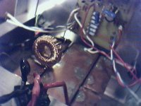
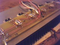
Here is the modified power board for the X Aleph.
Note the 1 watt power film resisters (2.2 ohms), they were the only value readily available to reduce the value of the source resisters to 0.5 ohms.
I have also carefully cut the tracks using a small grinder wheel on my PCB drill.
I have also dressed the boards with new leads, colour coded to avoid potential mistakes.
macka😉
Attachments
Here's the old Antrim transformer from the Aleph 2, 1000 Va 35+35 Antrim.
You need a huge Iron to solder those wires (double secondaries)
I am not sure what to do with it, door stopper?,boat anchor? tranni for a potential X Pass amp?, or I may post it the the trading post, dont know yet.
macka
Her indoors would kill me if she saw that sucker on the dining room table... Muhahahah
You need a huge Iron to solder those wires (double secondaries)
I am not sure what to do with it, door stopper?,boat anchor? tranni for a potential X Pass amp?, or I may post it the the trading post, dont know yet.
macka
Her indoors would kill me if she saw that sucker on the dining room table...
MuhahahahAttachments

Good work Macka you're working fast 🙂. But do you need the extra power of the larger X? You have very sensitive speakers I thought.
/Taco
/Taco
I wish I had the time (and the space!) to complete my projects.... (Aleph X - Pass Xover as soon as it will appear - My loudspeakers....)....
Cheers
Andrea
Cheers
Andrea
Thankyou,
Well it all happens late in the day....about 12.00 am!!
The new projects coming from Mr Pass are the reason for a move on.
I can't wait to see the Remote Pre amp and the Passover.
Yeah, that would be a big X Pass but they all are, and if I was to get way laid (poor choice of words) by that Gal, then I may have to consider smaller speakers of lower sensitivity..more waff friendly and a big amp like that would be real nice.
Beside, by then I could be making other things (hint hint) in the wee hours of the morning...a terrible thought...Muhahhaah
macka😎
Ps I anticipate at least one jealous email by morning!!🙂


Since many think that I am a "drop kick" whatever that is, let me take the full blame for this recent BIG misunderstanding.
-I am the stupid one-
I just thought they invented a new type of wire that was treated in some way as to render it insulated but without requiring the excess layer of combustible varnish.
In my work I see new type of materials I didn't know about on a daily basis.
-I am the stupid one-
I just thought they invented a new type of wire that was treated in some way as to render it insulated but without requiring the excess layer of combustible varnish.
In my work I see new type of materials I didn't know about on a daily basis.
- Status
- Not open for further replies.
- Home
- Amplifiers
- Pass Labs
- Aleph-X: High-Power Version