1. Is there a rule of thumb for calculating an effective value of the resistor in CRC Power supply filters? Is more better to the point- when your voltage gets too low or they heat up too much? Those issues I can calculate., but what is a reasonable value that is efective?
2. Now if you use a thermister, it has a range of course, I know Nelson has a mentioned the model he uses at some point. Can anyone help me track it down?
2. Now if you use a thermister, it has a range of course, I know Nelson has a mentioned the model he uses at some point. Can anyone help me track it down?
I think that the CRC is basically an attenuator, so the more resistance you have, the better (keeping in mind what you said about heat and voltage loss).
I don't know if this will help you, but the datasheet gives resistances for different percentages of max current through each device:
CL inrush suppressors
I don't know if this will help you, but the datasheet gives resistances for different percentages of max current through each device:
CL inrush suppressors
I didn't search hard enough
 here's some info:
http://www.diyaudio.com/forums/showthread.php?s=&threadid=759&highlight=thermistor
here's some info:http://www.diyaudio.com/forums/showthread.php?s=&threadid=759&highlight=thermistor
Hi power X Aleph buddys,
Your opinions and comments are welcome & appreciated.
I am considering the power supply for my Aleph 2 conversion to the X Aleph.
I plan to use 2 300 va 24 volt transformers per mono block configured with duaL bridge rectifiers for 25 volt rails under load.
My X Aleph design is based on 25 volt rails and for maximum power 139 watts @ minimum speaker impedance of 7 ohms.
Therefore the Peak current is about 6.5 amps and peak voltage 43.75ac (derived from the 25 volt rails).
Each half of the amp will need to deliver 21.87 volts peak and 6.5 amsp peak, allowing 2-3 volt losses on the fets and source resisitors so the 25 volt rails are appropriate.
Given the 50/50 current share of the Aleph CCS, the power supply will need to deliver 6.5 amps x (2) @ 25 volts dc = 325 watts .
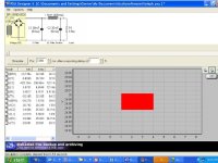
Here is the simulation on PS2. I have based this on the worst case senario (min voltage to the amp).
Using the existing capacitors 15,000 uf 63 volt x (4) per rail rated at about 20 amps each, I have opted for CLC filtering using 3Mh with 0.40 ohms DCR on the chokes (iron bar laminate sub woofer chokes). So I have 30,000 uf + 3Mh + 30,000.
The ripple is about 36millivots @ 6.5 amps.
Your comments an opinions most welcome.
macka
Your opinions and comments are welcome & appreciated.
I am considering the power supply for my Aleph 2 conversion to the X Aleph.
I plan to use 2 300 va 24 volt transformers per mono block configured with duaL bridge rectifiers for 25 volt rails under load.
My X Aleph design is based on 25 volt rails and for maximum power 139 watts @ minimum speaker impedance of 7 ohms.
Therefore the Peak current is about 6.5 amps and peak voltage 43.75ac (derived from the 25 volt rails).
Each half of the amp will need to deliver 21.87 volts peak and 6.5 amsp peak, allowing 2-3 volt losses on the fets and source resisitors so the 25 volt rails are appropriate.
Given the 50/50 current share of the Aleph CCS, the power supply will need to deliver 6.5 amps x (2) @ 25 volts dc = 325 watts .
Here is the simulation on PS2. I have based this on the worst case senario (min voltage to the amp).
Using the existing capacitors 15,000 uf 63 volt x (4) per rail rated at about 20 amps each, I have opted for CLC filtering using 3Mh with 0.40 ohms DCR on the chokes (iron bar laminate sub woofer chokes). So I have 30,000 uf + 3Mh + 30,000.
The ripple is about 36millivots @ 6.5 amps.
Your comments an opinions most welcome.
macka
Attachments
With some careful re wiring I should be able to use the exisiting power fet boards. Hopefully the Fets will also be a reasonable match as I previously matched them at 0.50 amps. But that remains to be seen.
The X Aleph will of course be running at about 1.00 amp each Fet @ 25 volts (3+3 IRF 244 per side) with 0.5 volts across the 0.47 ohms source resistors. All I need to do is carefully cut the track on the power boards in the centre, Thankfully, there is provision for this in the layout!!
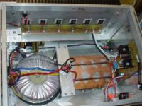
The two 300 va transformers will be stacked horizontally and the X board will replace the Aleph 2 board.
I'm sure it won't be that simple.
macka🙂
The X Aleph will of course be running at about 1.00 amp each Fet @ 25 volts (3+3 IRF 244 per side) with 0.5 volts across the 0.47 ohms source resistors. All I need to do is carefully cut the track on the power boards in the centre, Thankfully, there is provision for this in the layout!!
The two 300 va transformers will be stacked horizontally and the X board will replace the Aleph 2 board.
I'm sure it won't be that simple.
macka🙂
Attachments
Macka,
I know you don't care for MO but I think that your PS is not a good idea.
Specifically the DCR of the coil and the ~20ish watts it's going to dissipate in Cu losses alone. Plus if it's ironcore is probably going to saturate and generate even more heat. I guess you could split the core and have a mm or air but that will drop the inductance making the whole inductor idea pointless since what is doing the filtering work is the DCR not the XL.
Remember the dangers of having more iron in your amp too, more chance for EM noise.
Grataku,
On the contrary,
You have raised some practical issues which I had not considered.
These fancy models are great for simulation but dont always help in the real world always!!
The heat is a problem you are quite right. I hope the nylon former does not melt or catch fire .
I will have heat with CRC also, so I figure the CLC at least would offers less hum.
However, as you quite rightly point out there could also be problems with EM noise. I recall someone having noise issue in a previous post...I don't recall who and Mr Pass referring to coil mechanic noise.
This is not good for a nice class A amp where quietness is the key.
I'm note sure about the saturation of this type of bar (straight iron laminate choke), they use then for high power subwoofers.
Over the next few days I will try both methods out to see what works out the best using the Baby X to start with.
I have plenty of spare voltage but would prefer not to go below 25 volt.
Maybe the Thermistor is the best after all!!
macka
Macka,
I´m planing to use air chokes 1mH/0.12 ohms for up to 10A of total bias. These won´t saturate and the power loss isn´t that big. Using PSU2 this was the best I could get away with, without using too much space.
The setup will be 33mF-1mH-82mF
william
I´m planing to use air chokes 1mH/0.12 ohms for up to 10A of total bias. These won´t saturate and the power loss isn´t that big. Using PSU2 this was the best I could get away with, without using too much space.
The setup will be 33mF-1mH-82mF
william
wuffwaff,
any particular reason to have the bigger cap after the choke? I would think it's better to have the lower impedance arrangment, ie the lower ESR where there is more ripple current to be handled, which is in the cap immediately following the rectifier. If my memory is correct the ripple current distribution is about 80% to 20% between the first and the second cap.
any particular reason to have the bigger cap after the choke? I would think it's better to have the lower impedance arrangment, ie the lower ESR where there is more ripple current to be handled, which is in the cap immediately following the rectifier. If my memory is correct the ripple current distribution is about 80% to 20% between the first and the second cap.
Hi to everyone ,
I am getting started with my definitive version for my Aleph X .
Mono blocks version .
PSU +/- 24V , bias a little over 6 amps.Total of 12 IRFP240 per amp , with 0,5V or so on the 0,47 ohms source resistors .
I will set the AC current gain to 49 % .
I will use 3 heatsinks at 0,25 degrees per watt ,that on each mono block .
PSU will be 2 toroids ,2 bridges , one for each rail and total of 176.000 uF in 8 cans of 22.000 uF,arranged in C-R-C-R-C-R-C configuration .
But I wonder , on the XA 200 seems that Nelson uses zeners at the input preventing from electrostatic spikes , but I can see only 2 of them .Instead of 4 supposed to go between inputs and ground .
Is it possible to put only 2 of them, between gate and source of the 2 mos ?In that case is a 18 V model appropriate ? Does it protect the mos on both polarities of an eventual input spike ?
Thanks for answer 🙄
Regards
Macka,
the smaller capacity at the front is to reduce the input current peaks to a value around 20-30A. If I go much bigger the charge-current gets bigger and bigger without the voltage rising that much.
The bigger (and shorter) these current peaks are the more humm from the transformers.
The second bank of caps will be a lot of paralleled 3300uF and 2200uF. 80.000 (4x) is about what I´ve got laying around. I don´t think it´ll hurt to have a bit too much 😉
william
ww,
what currents do you mean? Currents at turn on?
I think your argument makes little sense. One thermistor on the transformer primary will solve that problem, on the other hand your arrangment will increase the power dissipated by the first cap giving worse ripple rejection and shorting the life of the cap.
I think he's referring to a continuous phenomenon, which isgrataku said:what currents do you mean? Currents at turn on?
I think your argument makes little sense. One thermistor on the transformer primary will solve that problem, on the other hand your arrangment will increase the power dissipated by the first cap giving worse ripple rejection and shorting the life of the cap.
usually called out as power factor. As the initial bank of capacitors
is increased, the peak of the charging pulse current tends to
get bigger. Also there is a law of diminishing returns as the
capacitance gets bigger, but as a practical matter, various
resistances step in to limit it, so really it is not that big an issue.
Personally, I just hang as many caps on supplies as I like, and
devil take the hindmost.

Grataku,
Nelson is right. The bigger the primary caps, the bigger the charging pulse. Making the first caps bigger than the 33mF has almost no effect on the voltage before the choke. Since the second bank of caps is the one that feeds the amp directly I think this is more important for sound quality.
And like I said before the bigger this current pulse the more mechanical humm you´ll get from the transformers.
william
William,
I like your design and will experiement with the power supply in the morning.
I appreciate you sharing your ideas.
This afternoon I bought a pile of 2.2 ohm film power resisters to lower the existing source resistors in the Aleph 2 boards to about 0.5 ohms (2 x 2.2 in parrellel with 1.0 ohm).
I also have some 6" long bolts to mount and stack the toriodals 24+ 24 and heap of those 15,000 uf 63 volt caps.
But for now I propose a toast to Mr Pass Birthday, I'm am sure he is doing same.
"Live Long and Prosper". (A quote from Mr Spock)
l'll bet those 24" woofers in the EL PIPE-O get an absolute hammering tonight via the X1000.
Three Cheers for Mr Pass

macka
I like your design and will experiement with the power supply in the morning.
I appreciate you sharing your ideas.
This afternoon I bought a pile of 2.2 ohm film power resisters to lower the existing source resistors in the Aleph 2 boards to about 0.5 ohms (2 x 2.2 in parrellel with 1.0 ohm).
I also have some 6" long bolts to mount and stack the toriodals 24+ 24 and heap of those 15,000 uf 63 volt caps.
But for now I propose a toast to Mr Pass Birthday, I'm am sure he is doing same.
"Live Long and Prosper". (A quote from Mr Spock)
l'll bet those 24" woofers in the EL PIPE-O get an absolute hammering tonight via the X1000.
Three Cheers for Mr Pass
macka
FLAMING HOT
Okay Grataku & William,
I have done the deed and watched my 1st 100 X Aleph go down the slip way on the Bench, fire extinguisher handy!!
The good news is there are no bangs, leaks, or smoke but Grataku is right about the chokes, they got very hot after a little while.
You know that smell of new electronics burning in is quite unmistakable.
The vital signs where very close to the simulations, the supply rails were 24.7 volts, 2.7 volts drop on the chokes (2.9 mH) @ 6.0 amps. The bias was right on 00.50 volts
The offset was a few millvolts at switch on and stable, the absolute offset was about 3 volts and dropped steadily as it heated up quickly with the heatsinks lying face down on the bench.
I appreciate your suggestions regarding the filtering issues, I will explore this a bit more. One solution I will try is to wind of a few more turns off the chokes to lower the dcr by 50 % and still have 1.5 - 2.00 mH.. This will ease the dissipation to about 10 watts per choke.
macka
Another run just for fun,
Waiting for everything to heat up, this time the heatsinks are up right.
I can smell the nylon formers on the chokes, a wet finger makes them sizzle, lucky lucky lucky.
Oopps they are starting to fume, smells toxic.... 3.78 volts across them @ 6 amps = 22.68 watts.
Well rather than wait for the smoke alarm ( 1.00 am here ) to kick in I'll review the chokes on the morning.
Thankyou all for your ideas and inspiration.
macka
One of the nice things about Class A amps, and balanced single ended Class A amps in particular is their constant current draw. This means that they are relatively immune to AC line impedance and you can insert resistance in series with the primary and even the secondaries to improve the noise and power factor. So what if you lose a couple watts?wuffwaff said:And like I said before the bigger this current pulse the more mechanical hum you´ll get from the transformers.
😎
I ran some more tests this morning and the amp is behaving well
Has anyone had any experience winding chokes with Ferrite Cores?
They seem like an efficient way to get high inductance from the least turns of coppoer wire. I have seen various high current RF chokes in the Farnell catalogue and wondered if this type of choke would be suitable?
This morning I have tried two filtering options using 30,000 + 30,000 uf. I am limited to this capacity at the moment but may go large later.
Firstly, I used CRC with 0.50 ohms from two parelled ceramic 1.O ohm 10 watt resisters, and then lowered the resistance to 0.33 ohms adding a 3rd 1.00 resister. They do not get to hot and the simullation say about 175 mv ripple.
I then tried winding off some turns on the iron bar woofer chokes to about 1.5 mh, the series resistance is now about 0.18 ohms for avoltage drop of 2.2 volts according to the similator with about 75 mv ripple. They get hot to touch but not toasted.
macka
- Status
- Not open for further replies.
- Home
- Amplifiers
- Pass Labs
- Aleph-X: High-Power Version