Re: dangerous
good for one channel
tenderland said:If I had a brain I would be dangerous....
ok how about sub the trany for
Hammond toroidal 182T12
300 va
24V ct @ 12.5A
good for one channel
Re: Re: My aleph-x finished with minor problem
Babowana,
There are no cap on circuit.
I prefer input transformer than cap.
Now I consider using input caps.
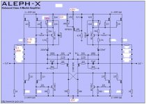
Here is my schematic. Sorry for unclean pic.
I modified few points since I can't raise bias above 0.53V on
source resister.
But now I only can raise bias 0.54V maximum.
I hope to raise bias upto total 8A.
I think heat sinks are satisfactory.
Power transformer 800VA each channel.
Is it right?
Babowana said:
Mr. Choi,
Your amp looks much better than usual DIY.
Very nice finish!
By the way,
does the original design have any input coupling cap?
Where?

Babowana,
There are no cap on circuit.
I prefer input transformer than cap.
Now I consider using input caps.
Here is my schematic. Sorry for unclean pic.
I modified few points since I can't raise bias above 0.53V on
source resister.
But now I only can raise bias 0.54V maximum.
I hope to raise bias upto total 8A.
I think heat sinks are satisfactory.
Power transformer 800VA each channel.
Is it right?
Attachments
Re: Re: Re: My aleph-x finished with minor problem
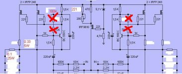
If you cut off the resistors cross-marked in red,
you would get about 0.66V across each source R of 0R33.
It will give total 8A bias you want to have.
By the way, I don't understand the input cap yet.
Where are you going to put?
Chois¢â said:But now I only can raise bias 0.54V maximum.
I hope to raise bias upto total 8A.
If you cut off the resistors cross-marked in red,
you would get about 0.66V across each source R of 0R33.
It will give total 8A bias you want to have.
By the way, I don't understand the input cap yet.
Where are you going to put?
Attachments
Thank you Babowana
I'll try to raise bias.
I should put cap between input terminal and 10K
resister.
When selected RCA input, - terminal connect to ground
after cap. That's I know from this thread.
But I'm searching proper input transformer available
both XLR and RCA input selectively.
I'll try to raise bias.
I should put cap between input terminal and 10K
resister.
When selected RCA input, - terminal connect to ground
after cap. That's I know from this thread.
But I'm searching proper input transformer available
both XLR and RCA input selectively.
Attachments
Chois¢â said:When selected RCA input, - terminal connect to ground
after cap. That's I know from this thread.
To block DC coming up from the ground?
The A-X amp has so poor CMRR at the differential input?
I didn't know it. Disappointing . . .
If you present single-ended DC at the input, the Aleph-X will obediently amplify it. If the same DC voltage is present at both the + and - inputs, it will reject it. That's the definition of CMRR (and direct coupling, too, for that matter).
I use a tube preamp, which has DC blocking caps at the output. For me, it's a non-problem. If your preamp has DC offset at the output, then DC blocking cap(s) at the input(s) of the Aleph-X will solve the problem.
Or you could take a look at why your preamp is delivering DC.
Either way, it's a non-problem.
Grey
I have about 0.2 mV offset on my DAC's outputs (differential could be up to 0.3 mV). Is that too much to direct-couple to the Aleph-X?
Re: Re: Re: Re: voltage question
Thnx, Nixie, that's exactly what I wanted!
As I am more alien to the search function than others (or maybe I'm just lazy) I'll go right ahead ignoring your subtle hint and just ask you a follow up:
What about toroids? And what if I happen to be living in Sweden where we have 50Hz mains? (Luckily I'm not running it off our railway grid which is plodding along at sixteen and a third Hz)
Hilbert
Nixie said:Cross-sectional core area (in an EI core obviously that's the center bar of the E, or the sum of its two outer horizontal bars) is proportional to the square root of the VA. Assuming standard safety margin in avoiding core saturation, common core material, and 60 Hz mains, with area in cm^2, the constant of proportionality is around one.
Of course, such information has been posted many times on this forum already. Still, I know the 'search' function is a technology alien to most minds and its logic is difficult to master.
Thnx, Nixie, that's exactly what I wanted!
As I am more alien to the search function than others (or maybe I'm just lazy) I'll go right ahead ignoring your subtle hint and just ask you a follow up:
What about toroids? And what if I happen to be living in Sweden where we have 50Hz mains? (Luckily I'm not running it off our railway grid which is plodding along at sixteen and a third Hz)
Hilbert
As far as I know, toroidal cores are generally made from the same set of materials, so it would be the same. For 50 Hz, the cores would be a bit larger than those designed for 60 Hz operation.
After the few problems I had with my build that I asked about a few pages back, I got my amps going 🙂
Specs are - 16V rails, 4.2A bias, 4 fets, for 50W into 8ohm. Straight DC coupling single ended inputs with a small protection circuit I whipped up that cuts out a relay on the speaker terminals if the relative DC offset is too much. Testing with my portable mp3 player I get only 20mV on the output at most and I set the circuit to trip at about 120mV
Here is the schematic of the protection circuit, it also includes a flip flop to run a pushbutton power-on switch which drives a solidstate relay that switches the mains power for the main transformer for the amp which includes zero crossing in the ss relay to help with turn on transients, and the whole circuit runs off a second small transformer
I designed and etched the PCB's myself
And built as a complimentary pair, the chassis' are a mirror image of each other
One channel isn't completed in the pictures there, but it has been finished now
Specs are - 16V rails, 4.2A bias, 4 fets, for 50W into 8ohm. Straight DC coupling single ended inputs with a small protection circuit I whipped up that cuts out a relay on the speaker terminals if the relative DC offset is too much. Testing with my portable mp3 player I get only 20mV on the output at most and I set the circuit to trip at about 120mV
Here is the schematic of the protection circuit, it also includes a flip flop to run a pushbutton power-on switch which drives a solidstate relay that switches the mains power for the main transformer for the amp which includes zero crossing in the ss relay to help with turn on transients, and the whole circuit runs off a second small transformer
I designed and etched the PCB's myself
An externally hosted image should be here but it was not working when we last tested it.
An externally hosted image should be here but it was not working when we last tested it.
And built as a complimentary pair, the chassis' are a mirror image of each other
An externally hosted image should be here but it was not working when we last tested it.
An externally hosted image should be here but it was not working when we last tested it.
An externally hosted image should be here but it was not working when we last tested it.
One channel isn't completed in the pictures there, but it has been finished now
Originally posted by Nixie
I have about 0.2 mV offset on my DAC's outputs (differential could be up to 0.3 mV). Is that too much to direct-couple to the Aleph-X?
No, your amp should hardly notice it, or at least mine doesn't.
Hifizen told me once that direct coupling if there's DC offset will cause the amp to draw significant DC current from the DAC's output stage. The buffer's output impedance is maybe as high as 600R, so I don't know if that's a problem.
Looks like 10K on the PCB version.
I'm curious, what happens to a DC-coupled input if there's a significant DC offset on the Aleph-X output?
Also, I'm using balanced without ground connection through the XLR cable (though of course both amp and DAC are earthed). That avoids ground loops and the cable geometry, but allows a potentially higher common mode offset.
p offed
I just purchased a large quantity of IRfp044 mosfetts from Ebay.
To my dismay they came shipped all in one small bag ,clear plastic not
antistatic. Is this something to be concerned about , I have a mind to send them back.
J
I just purchased a large quantity of IRfp044 mosfetts from Ebay.
To my dismay they came shipped all in one small bag ,clear plastic not
antistatic. Is this something to be concerned about , I have a mind to send them back.
J
You might want to test a few under actual load conditions. I once had several Mosfets that tested fine under light load, but failed under heavy load.
- Home
- Amplifiers
- Pass Labs
- Aleph-X builder's thread