Hi Ian,
thanks for your reply!
I've read this new information yesterday evening. It is difficult to interpret... not really a new information...
Some more sentences to my questions:
1) The stand by consuption must be higher (approx 40-50W). Half get lost in the N-ch devices, a bit fewer in the SE-bias resistors (they are responsible for the high stby consuption because they are not switched of) and the rest in the P-ch. (INT150 standby 45W)
2) There is no separate supply for the front end! Only possibility I found are the bootstrapping capacitors. But I don't know if this could work!?
3) Just an idea!
4) My calculations show approx 150mW RMS (with 55V peak). I have asked that because I can see 10k/3W resistors in the bias circuit on a picture - thought they are the resistors which Nelson had talked about. Strange to say 3W!???
5) I am quite sure that you can use a thermistor to eliminate a good portion of the bias drift. But I have no good idea at the moment where to put it in.
The second possibility is to use it as a current limiter for the output stage.
6) I don't know if you just can put a resistor in parallel to the voltage reference. This will generate a current source...?
7) Have an idea: It could come from the rectifier and supplies current to the coil of the relay. On this way you can isolate the switching circuit a bit from the main supply and it is independant from the charging conditions of the caps.
Regards
Dirk
Ian Macmillan said:Dirk,
Just noticed this in the XA.5 information on the Passlabs web site:
"New bias circuit – A newly developed bias generator has eliminated three sources of variation in bias current in the output stage. It also allows approximately 20% greater power output for a given supply voltage"
so perhaps you are on to something with your thermistor idea. Certainlly worth thinking about.
Ian.
look for babozen
Hallo Grey and all the others
The idea of bootstrapping and using the TL431 as voltage bias reference comes from Firstwatt.
The rest of the VBC seems to be different:
The stages are not coupled with caps, because you need trimmers before the output stage to adjust the offset. The two in the front end would be out of work.
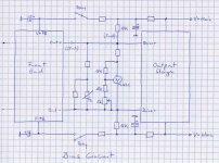
I have drawn down an idea - perhaps this will function:
The bias circuit is made of a voltage reference with a small resistor in series. On this way you can vary the bias voltage a bit dependent from the current.
Means when it is driven by the front end current of about 27mA it reaches a higher value as when it is driven in stand by mode by only the 10k resistors.
Also there is a ("boxed") thermistor network in parallel to the voltage reference network for two reasons:
It handles half of the dissipation (approx. 100mW) (only in power mode) and it can vary the voltage bias dependent on its temperature for faster warm up and less bias drift.
Hope that somebody will answer to it if this could work...
...perhaps with an idea how I can implement bootstrapping capacitors or another network for more output voltage swing.
(without a separate higher front end voltage)
Greatings and nice sunday
Dirk
The idea of bootstrapping and using the TL431 as voltage bias reference comes from Firstwatt.
The rest of the VBC seems to be different:
The stages are not coupled with caps, because you need trimmers before the output stage to adjust the offset. The two in the front end would be out of work.
I have drawn down an idea - perhaps this will function:
The bias circuit is made of a voltage reference with a small resistor in series. On this way you can vary the bias voltage a bit dependent from the current.
Means when it is driven by the front end current of about 27mA it reaches a higher value as when it is driven in stand by mode by only the 10k resistors.
Also there is a ("boxed") thermistor network in parallel to the voltage reference network for two reasons:
It handles half of the dissipation (approx. 100mW) (only in power mode) and it can vary the voltage bias dependent on its temperature for faster warm up and less bias drift.
Hope that somebody will answer to it if this could work...
...perhaps with an idea how I can implement bootstrapping capacitors or another network for more output voltage swing.
(without a separate higher front end voltage)
Greatings and nice sunday
Dirk
Attachments
This is a desperate call for help.
Hello,
I am Ralf from Germany and try to build an Aleph X. I am quite experienced in DIY (e.g. I successfully built an Alpeh P1.7) but I fear the Aleph X is beyond my possibilities. Without support form you this will be the biggest money to trash bin project in my life.
My Aleph X is a standard Gray/Rollins except for D1 which is built according to this http://www.r-stens.de/diy/AlephX/Input/Input.pdf
My PCBs are self made (using Target) but I can’t guarantee that there a no bugs in the wiring.
I have +- 16 V rail.
Q 6a is G 9.0, D 2.6, S 13.2
The problem I have is Q1
Q1 is G -11.0, D16.0, S -14.0
Q10 is nearly the same
I cannot let it run for more than a few second because then R1/4 get so hot they start smoking. So it is really hard at the moment to get measurements as I don’t want lose my carefully matched resistors.
I really hope someone here is willing to help me and that I am able to transform your help in a running amp.
Best wishes
Ralf
P.S.
I forgot to mention:
I made a measurment before I put in Q1/10, Q 2/11 and I had for Q6: S 13.2, D 3.96
I forgot to mention:
I made a measurment before I put in Q1/10, Q 2/11 and I had for Q6: S 13.2, D 3.96
Hi Zen Mod,
please give me another hint in which thread and post I should look for babozen.
Need more ideas...... have read Zen V5, A75 part 1+2 and other stuff without results...
Regards
Dirk
please give me another hint in which thread and post I should look for babozen.
Need more ideas...... have read Zen V5, A75 part 1+2 and other stuff without results...
Regards
Dirk
Hello,
I forgot to mention: I use 2SC2547 instead of the MPSA18 for Q3/8/4/9. Can this be the cause that Q2/9 open up?
Best wishes
Ralf
I forgot to mention: I use 2SC2547 instead of the MPSA18 for Q3/8/4/9. Can this be the cause that Q2/9 open up?
Best wishes
Ralf
noisefree said:Hi Zen Mod,
please give me another hint in which thread and post I should look for babozen.
Need more ideas...... have read Zen V5, A75 part 1+2 and other stuff without results...
Regards
Dirk
http://www.diyaudio.com/forums/showthread.php?postid=998738#post998738
noisefree said:Thanks
have found thermistor networks...
Dirk
Perhaps you could share... I couldn't find them despite the reference.
Ian.
"It also allows approximately 20% greater power output for a given supply voltage"
This quote would seem to imply the use of bootstrapping, likely in the same form as used in the F4.
It would also explain the lack of (atleast to my eyes) a separate supply for the input/driverstage circuits and a little coincidentally fit well with the proposed 10K resistor to each rail from bias network.
Hi Ian,
no problem, have a look in the thread "Papa! I want to have Zen V5." Post 183.
But you will find nothing new...
There are explanations of resistor-thermistor-networks. No hint for the voltage bias you need for this kind of follower stage. (in a ZV5 are no followers)
Perhaps there are some other hints in this thread...?....have not read the whole...
(You are the guy with the "Macmillan resistor" idea in an AX aren't you?
...don't know if you have read it some posts before......hint: no need for it in this design)
Tazzz,
yes the 20% quotes for bootstrapping.
But the question is how to implement it!? The front end and bias circuits of the two amps are different. Also the 10k resistors in a F4 are necessary to feed the voltage source. My bias drawing above only need the 10ks in stand by mode.
...and I am wondering about the use of 3W power versions?
Short resume:
We need a VBC which has to work in the following way:
(the values are just an example)
- In stand by mode the bias voltage has to be 7,6V
- In cold power mode the bias voltage has to be 8,1V
- In warmed up power mode the bias voltage has to be 8V
- Also we need some kind of bootstrapping for more voltage swing
Regards
Dirk
noisefree said:(You are the guy with the "Macmillan resistor" idea in an AX aren't you?
...don't know if you have read it some posts before......hint: no need for it in this design)
Yeah, that's me. I only reinvented NP's idea though and I didn't really appreciate that I had discovered the 'answer' at the time.
Why do you say that these are not required in the AX100.5? I'm not saying that they are but I would have thought that the circuit would still be prone to common-mode offset without. Simulation suggests the circuit is still quite sensitive in this respect.
Ian.
noisefree said:Hi Ian,
thanks for your reply!
I've read this new information yesterday evening. It is difficult to interpret... not really a new information...
Some more sentences to my questions:
1) The stand by consuption must be higher (approx 40-50W). Half get lost in the N-ch devices, a bit fewer in the SE-bias resistors (they are responsible for the high stby consuption because they are not switched of) and the rest in the P-ch. (INT150 standby 45W)
2) There is no separate supply for the front end! Only possibility I found are the bootstrapping capacitors. But I don't know if this could work!?
3) Just an idea!
4) My calculations show approx 150mW RMS (with 55V peak). I have asked that because I can see 10k/3W resistors in the bias circuit on a picture - thought they are the resistors which Nelson had talked about. Strange to say 3W!???
5) I am quite sure that you can use a thermistor to eliminate a good portion of the bias drift. But I have no good idea at the moment where to put it in.
The second possibility is to use it as a current limiter for the output stage.
6) I don't know if you just can put a resistor in parallel to the voltage reference. This will generate a current source...?
Sorry, its taken me a while to get around to responding to these questions.
1) Good point, I had forgotten about the SE bias resistors. I don’t know how much SE bias NP uses so it is difficult to come up with a specific figure for standby current. If the INT150 is 45W I don’t see why the XA100.5 would be much different.
2) Do you know this for sure or are you deducing from a picture or similar? I assume you don’t have access to a real live XA100.5 otherwise you would already have all the answers. The front end supply could come from a voltage doubler arrangement and hence might not be very visible. However, if you are right then I agree that some form of bootstrapping is most likely. I’m not sure how to implement this with a UGS front end but I’ll give it some thought. I’m also not sure that the production unit is DC coupled although I take your point about the front end trimpots. The earlier X series had a response down to DC but the current versions don’t suggesting perhaps that they have some AC coupling...
3) .
4) I can see the various 3W resistors in a picture of the AX100.5 innards but I don’t know what they do, nor whether they are 10k in value.
5) I can’t see the thermistors you mention but perhaps my picture is not so good. I’m guessing it will be in the reference setting part of the TL431 if it is for bias drift. Then again, I thought the TL431 was pretty stable with respect to temperature anyway. Perhaps it has more to do with arranging a lower value of bias when the current is low, e.g. at standby?
6) I don’t think a parallel resistor across the TL431 will impact its performance much if the value is not too small. A shunt voltage regulator should have a low internal resistance. I’ve no idea whether this is done in the XA100.5 though. It doesn’t sound hugely likely to me.
Ian.
- In stand by mode the bias voltage has to be 7,6V
- In cold power mode the bias voltage has to be 8,1V
- In warmed up power mode the bias voltage has to be 8V
Is it not just a matter of adjusting the resistor who sets the voltage for the TL431?
Possibly by switching in an extra resistor in parallell for the standby mode and connecting a thermistor + a small resistor network to set the needed change in resistance with temperature.
(in event of confusion, not in parallell with the TL431 in its entierly just with the voltage setting resistor, the tl431 can be seen as similar to an lm317 with 2.5v reference voltage)
- Also we need some kind of bootstrapping for more voltage swing
I think ~20% extra corresponds pretty well to the extra swing you would get by lifting half the necessary voltage to bias the fets (applied exactly like the two caps between the jfets and the mosfets in the F4)
Ian,
1) Yes I agree with you. Both uses nearly the same SE current
2) Have testmagazines from 30.5 und INT with some pictures.
I'm sure that the 30.5 uses no seperate windings and no voltage doubbler and only bridgeable caps at the inputs.
Current X.5 versions have input caps too and a "normal" voltage bias circuit (MOS GS-Ref) and switchable (with a transistor) SE-bias resistors (for stand by turn off).
4) There are a lot of 3W resistors. I interpretate the arrangement of them in the following way: 6 resitors for supply filtering of the front end, one for the meter, two I don't know and two 10k (which I can see) for every voltage bias circuit.
5) It isn't a CL60 and it is placed between one of the VBC elcaps and the three 1/4W resistors bank. Have a look in the jap.manual again.
Sure the drift of the TL431 is absolutely minimal. That is not the point.
The network around it should give the VBC the "right drift" for faster warm up / constant output bias. Also the serial resistor should reduce the bias voltage when it is only driven by the 10k resistors in stand by mode.
Dirk
Tazzz said:[B
- Also we need some kind of bootstrapping for more voltage swing
I think ~20% extra corresponds pretty well to the extra swing you would get by lifting half the necessary voltage to bias the fets (applied exactly like the two caps between the jfets and the mosfets in the F4) [/B]
Not sure I understand your last point about applying in exactly the same way as the F4. The F4 uses a pair of source followers to drive the PP output followers whereas the XA uses heavily degenerated common source FETs. Where should I connect the bootstrap capacitors in this arrangement? Presumably it is not appropriate to modulate the supply for the entire front end?
Ian.
Ian,
I agree with you. You cannot connect the caps in the same way as in the F4. Front end stages are completely different.
When there is bootstrapping applied than there must be a possibility to do that with the front end voltage.
Have searched for bootstrapping in the internet and found a lot of information for switching supplies.
The only short and good explanation comes from Nelson in this forum! Unfortunately not helpfull for this application :-(
And sorry, I have given you the wrong hint with the Macmillan-resistors!
Right direction: DIY progress report ; Post 1576 and 1579
Greatings
Dirk
noisefree said:
And sorry, I have given you the wrong hint with the Macmillan-resistors!
Right direction: DIY progress report ; Post 1576 and 1579
I am not sure whether to take NP's answer in post 1579 as nobody knows, or that there are no such resistors in the XA100.5. I take it you believe he meant that they are not required and I think I agree.
Ian.
- Home
- Amplifiers
- Pass Labs
- Aleph-X builder's thread