power supply
I am trying to design the power suply for an Aleph X.Rail voltage is +/-
15 v . From the wiki and other posts a crc pi filter is a good choice.
two caps to ground seperated by a .15 ohm resistor. Is the total capacitance simply the additon of the two caps? and do you usualy use equal values.?
J
I am trying to design the power suply for an Aleph X.Rail voltage is +/-
15 v . From the wiki and other posts a crc pi filter is a good choice.
two caps to ground seperated by a .15 ohm resistor. Is the total capacitance simply the additon of the two caps? and do you usualy use equal values.?
J
Re: power supply
www.duncanamps.com
download PSUd for free and play with..........
then everything be clearer to you...
btw-answer on all your questions is ~ yes
tenderland said:I am trying to design the power suply for an Aleph X.Rail voltage is +/-
15 v . From the wiki and other posts a crc pi filter is a good choice.
two caps to ground seperated by a .15 ohm resistor. Is the total capacitance simply the additon of the two caps? and do you usualy use equal values.?
J
www.duncanamps.com
download PSUd for free and play with..........
then everything be clearer to you...
btw-answer on all your questions is ~ yes
The total capacitance depends on your intentions. If you're the advertising department, it all counts, right down to the smallest cap in the front end. In operational terms, I only count the final capacitance after the resistor in terms of a CRC--the R slows the delivery of charge from any capacitance upstream sufficiently that I don't think of it in terms of output to the speaker terminals. Think of it in terms of ESR--with a very heavy R component. Like a poor quality cap.
A matter of perspective: Is the power supply's job to filter out residual ripple and spikes from the transformer and diodes...or is it energy storage for the amplifier circuit?
The answer is yes. And more besides.
If you're looking at it in terms of smooth DC, then the capacitance in front of the resistor is a crucial member of the team. If you're looking at it in terms of energy storage, then the second cap is the star. As a practical matter, anyone building a CRC filter usually buys identical caps, puts a resistor between them, and calls it quits.
The Aleph-X is kind in the sense that its current draw sums nearly to DC. As such, you don't have to get so flustered worrying about the ability to handle peak currents. Give it good quality DC and it will be a happy amp.
Grey
Re: power supply
I do the simple addition.
And, I once thought about different values,
expecting maximization of efficient combination of R/C.
That time, Papa and Grey were against my thought.
Everyone usually uses equal values.
I follow the same 🙂
tenderland said:Is the total capacitance simply the additon of the two caps? and do you usualy use equal values.?
I do the simple addition.
And, I once thought about different values,
expecting maximization of efficient combination of R/C.
That time, Papa and Grey were against my thought.
Everyone usually uses equal values.
I follow the same 🙂
crc
Thank you for the response and I apologize for the rather basic question. This is my first solid state project and I will do my best researching difficulties on my own.
Jeff
Thank you for the response and I apologize for the rather basic question. This is my first solid state project and I will do my best researching difficulties on my own.
Jeff
Re: crc
my answer was more related to fact that you'll have more benefit if you learn and know .........as we all do every day 😉
play with psud,and ask if you need to;
in that way you can try various things and see what differences are
happy diy-ing 😉
you're wellcome to ask questions;tenderland said:Thank you for the response and I apologize for the rather basic question. This is my first solid state project and I will do my best researching difficulties on my own.
Jeff
my answer was more related to fact that you'll have more benefit if you learn and know .........as we all do every day 😉
play with psud,and ask if you need to;
in that way you can try various things and see what differences are
happy diy-ing 😉
psud
I have installed PSUD and I am having some difficulties.
crc pi filter
source resistance = 20 Ohms(TRANSFORMER)
c= 68000uf *2
I am not sure what to use for the load resistance.
I can calculate a figure for the resistance based on power and current
but it seems low and gives me bad results in psud. Also if I use a resistnace of .25 ohms for the pi filter I get bad data.
I can get resonable results when I use a resistance of .15 and a rather large load resisrance.
Thanks
J -(plugin along)
Source resistance 20 ohms?!
Did you actually measure that on the secondaries? Must be a very small transformer...
Did you actually measure that on the secondaries? Must be a very small transformer...
Re: psud
use help for learn how to calculate xformer impedance ;I'll write that here for you,but I always forget that ..and always must look in help,too 😉
use CCL (current sink,current source ,whatever) as load -instead of resistor
tenderland said:I have installed PSUD and I am having some difficulties.
crc pi filter
source resistance = 20 Ohms(TRANSFORMER)
c= 68000uf *2
I am not sure what to use for the load resistance.
I can calculate a figure for the resistance based on power and current
but it seems low and gives me bad results in psud. Also if I use a resistnace of .25 ohms for the pi filter I get bad data.
I can get resonable results when I use a resistance of .15 and a rather large load resisrance.
Thanks
J -(plugin along)
use help for learn how to calculate xformer impedance ;I'll write that here for you,but I always forget that ..and always must look in help,too 😉
use CCL (current sink,current source ,whatever) as load -instead of resistor
Re: psud
I just choose R
having the value greater than or equal to 10 x 1/(6.28xfxC),
where f= ripple frequency (100 or 120Hz)
Of course, I should remember checking the watage rating of the R
tenderland said:crc pi filter
I just choose R
having the value greater than or equal to 10 x 1/(6.28xfxC),
where f= ripple frequency (100 or 120Hz)
Of course, I should remember checking the watage rating of the R
power supply design
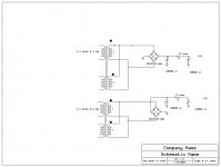
Well after some work I have come up with a power supply design for the Aleph x low power version. The transformers are plitron 160 va
24 v 3.33 amp dual secondary wired in parrallel, one trany one bridge for each rail. Followed by a CRC filter (two 100000uf caps and a .15 ohm resistor). Is this to elaborate , and would there be better symetry if I only used one 12 v center tap trany for each mono block instead of 2?
j


What you've drawn isn't parallel secondaries. The tops and bottoms of each secondary should be tied together.
For that matter, just parallel the two transformers and be done with it.
As far as filtering, try to find some inductors. Consider winding them yourself if necessary. Then use an LC filter--or LCRC if you want. The L at the beginning will do a very tidy job of knocking some of the surplus voltage off the top, and give you more current capability in the bargain, not to mention lowering the ripple the caps see, etc.
Grey
Your schematic is a bit confusing. That's not how you draw dual secondary transformers. The core would be shared, and when you're not indicating the phase of the secondaries with phasing dots, one naturally assumes that they're in the same orientation, which in your case would make them in reverse phase to each other. I hope you understand you have to get the right phase when you're hooking up multiple secondaries in series or parallel.
- Home
- Amplifiers
- Pass Labs
- Aleph-X builder's thread