Porn will follow when I get something that works a little more reliably...
Edit - the boards for the next rev of the DC-DC should be arriving on Monday. Though more complex, the non-self oscillating converter works efficiently, with no back talk.
Edit - the boards for the next rev of the DC-DC should be arriving on Monday. Though more complex, the non-self oscillating converter works efficiently, with no back talk.
Last edited:
OK, dubious porn here - This is the crazy cat's cradle that represents my effort to construct a minimal parts count self-oscillating DC-DC converter to generate the negative rail for the Aleph Mini-Me. Things look OK, except that the converter does not like to properly come up into a constant current load when the input voltage is applied slowly. Maybe this will change if I just slam on the DC supply feeding the converter at full voltage. If there's a dead zone between the initial application of voltage and actual current draw , this might allow the DC-DC to come up without issue.
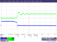
When the converter does come up properly, it's a beast. Switching times are pretty fast for a basic self-oscillating DC-Dc.
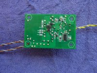
First off, a rough picture of the crazy cat's cradle that's the converter so far.
Next up, some drain waveforms, including an expanded view showing some fairly fast switching for a self-oscillating converter.
When the converter does come up properly, it's a beast. Switching times are pretty fast for a basic self-oscillating DC-Dc.
First off, a rough picture of the crazy cat's cradle that's the converter so far.
Next up, some drain waveforms, including an expanded view showing some fairly fast switching for a self-oscillating converter.
Attachments


Interesting - If the DC-DC is turned on with the voltage up full, it starts into a current source load. Next up - adjusting the value of speed-up capacitors to optimize drive levels. I was lazy and did not look up the data sheet for the IRFZ14. I assumed the gate capacitance was ~1000pF - it's actually around 300pF. This means I can substantially reduce the value of the drive speed-up capacitors. I will try reducing them to 220pF from 1000pF.
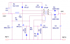
I just got my boards today for the downsized version of the negative bias DC-DC converter. This is a driven solution instead of self-oscillating, so it's more complex. However, the design already works without a lot of farting around. It's likely more efficient as well as there is no energy waste from driving the main transformer core back and forth into hard saturation.
I also have a vacuum/sand hybrid RIAA/lineamp in the works. I may power that project using a Baxendall oscillator fronted with a synchronous buck converter. Look up the Baxendall oscillator if you're curious - easy to find info on same with friend Google.
I also have a vacuum/sand hybrid RIAA/lineamp in the works. I may power that project using a Baxendall oscillator fronted with a synchronous buck converter. Look up the Baxendall oscillator if you're curious - easy to find info on same with friend Google.
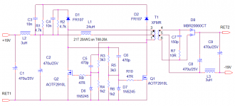
Here's the next pass on the current fed Royer DC-DC design, with an improvement on the drive characteristics, and a picture of the drain waveforms. The snubber will need some work to damp the spike on the drain waveforms, or I'll just use 100V mosfets like my other DC-DC.
Attachments
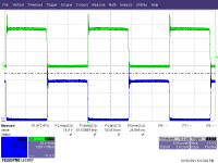
I suspect that the drain spike is due to insufficient overlap between the two drive phases. Adding some turn-off delay to the drive may help. More later, when I get a chance to fiddle...
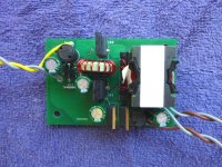
Here is a partless wonder saturating core converter for converting a positive voltage from a switching adapter to a negative voltage. No switching controller is necessary, as this is a variation on the classic Royer saturating DC-DC converter, with an inductor in the XFMR primary center tap to reduce the shoot-through current caused by the saturating transformer.
Boards for this are in fab at PCBWAY.
Boards for this are in fab at PCBWAY.
Attachments
- Home
- Amplifiers
- Pass Labs
- Aleph Mini-Me