Not sure if I should start a new thread for this so I'm putting it here.
Was enjoying my JZM over the holidays and it suddenly belched as pretty loud buzzing sound, spewed some magic smoke and blew a fuse. Took it to the bench, replaced the fuse and tested it on the variac. No problems. Came back to life and seemed stable up to 120V. Took it back and plugged it into the system, listened for a while and she popped the fuse again (along with the buzzing).
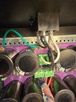
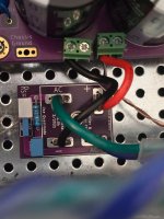
So back to the bench. Poking around, I noticed that the thermistor on the (Thatcher) power supply board was pretty crispy.
So I dug through the parts back and managed to find a spare CL-60 and soldered it in. The old one basically fell apart in my fingers.
So, fired it up on the Variac again and seemed to be working (no load or speakers). DMM says the power supply is putting out 24V as expected on both sides. Let it heat up for a while and everything seems to be OK. Back in the system....
Not so much. The amp basically emits a loud buzz in both channels now. Doing a little investigating, I am seeing around 5V DC across the speaker terminals. Checked to make sure the Mosfets were properly isolated from the heat syncs, double checked the power supply output, but that's about the extent of it.
Not sure where to go from here.
Was enjoying my JZM over the holidays and it suddenly belched as pretty loud buzzing sound, spewed some magic smoke and blew a fuse. Took it to the bench, replaced the fuse and tested it on the variac. No problems. Came back to life and seemed stable up to 120V. Took it back and plugged it into the system, listened for a while and she popped the fuse again (along with the buzzing).
So back to the bench. Poking around, I noticed that the thermistor on the (Thatcher) power supply board was pretty crispy.
So I dug through the parts back and managed to find a spare CL-60 and soldered it in. The old one basically fell apart in my fingers.
So, fired it up on the Variac again and seemed to be working (no load or speakers). DMM says the power supply is putting out 24V as expected on both sides. Let it heat up for a while and everything seems to be OK. Back in the system....
Not so much. The amp basically emits a loud buzz in both channels now. Doing a little investigating, I am seeing around 5V DC across the speaker terminals. Checked to make sure the Mosfets were properly isolated from the heat syncs, double checked the power supply output, but that's about the extent of it.
Not sure where to go from here.
Attachments


If that ground-isolating thermistor burnt up, you have a major AC wiring fault somewhere.
For your safety, DO NOT PLUG IT IN AGAIN until the fault is located and fixed.
For your safety, DO NOT PLUG IT IN AGAIN until the fault is located and fixed.

This is kind of what I was hoping to get some help with. The amp was working fine until it suddenly wasn't.until the fault is located and fixed.
Are you suggesting that the thermistor was failing over time due to an undetected AC fault and it finally just fried completely? Or that there was some sudden change (loose wire, something fell in the top of the chassis and shorted something, IEC wiring suddenly failed etc.)?
Sorry to be dense. Newb.
Are you suggesting that the thermistor was failing over time due to an undetected AC fault and it finally just fried completely?
That's quite likely. The thermistor that burnt up is not designed to ever have current in it unless there's something wrong. That it got hot enough to burn up is indication of something quite bad.
Where to begin? Remove the entire PSU from the chassis and inspect.
10-4That's quite likely. The thermistor that burnt up is not designed to ever have current in it unless there's something wrong. That it got hot enough to burn up is indication of something quite bad.
Where to begin? Remove the entire PSU from the chassis and inspect.
Thank you very much for the assist.
most likely nothing having with channel pcbs at all ...... triple check isolation of anything PSU against the case
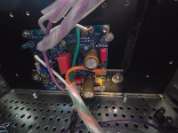
from recent reading - snubber pcbs at KBPC bridges are suspicious - be sure that no (bottom) pcb trace on them is tight to bridge case ....... and be sure that nut for bridge is bolted directly to bridge, no pcb being in sandwich
give us closer pic of that detail
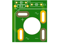
as illustration, here is how that is made properly
from recent reading - snubber pcbs at KBPC bridges are suspicious - be sure that no (bottom) pcb trace on them is tight to bridge case ....... and be sure that nut for bridge is bolted directly to bridge, no pcb being in sandwich
give us closer pic of that detail
as illustration, here is how that is made properly
Attachments

Last edited:
Thank you. Will do tonight.triple check isolation of anything PSU against the case
for clarity - above possible culprit to intermittent short causing smokebe sure that no (bottom) pcb trace on them is tight to bridge case
and this
nut for bridge is bolted directly to bridge, no pcb being in sandwich
important because - if there is any wiggle, bridge will die in future, without sufficient pressure to base, thus no thermal flowing out
doesn't matter how small dissipation seems, it will go puff, without proper heatsinking
in short - proper bolting, split washer, and only then there is no fear from heat and heat cycling
give us closer pic of that detail
Zen Mod said:
nut for bridge is bolted directly to bridge, no pcb being in sandwich
If I'm reading you correctly, I am doing exactly what you suggest not to do correct?
Attachments

Last edited:
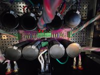
in last several days it was shown that one snubber pcb ic critical, not having big enough hole for washer and nut, so bolting force applied to pcb, then to bridge itself; that's big no-no
besides, same pcb is having problem with bottom traces, most likely having contact with top edge of bridge metal case, if care is not taken to make a clearance
I believe you have exact problematic pcbs shown there
I believe @birdbox posted about problematic pcbs, or he replied, at least
remedy is to drill big enough hole (for washer and nut) in center of pcbs, and ensure there is a clearance while soldering to bridge
btw. from your pics I can't even see soldering to bridge AC pins?
remove wires, unbolt bridges and inspect
post conclusions and clear pics here
Yes, I had a short from the rectifier snubber board to the rectifier metal case. Zen Mod is spot on with how to avoid in future. Here's the thread where I posted my recent issue and suggested resolution.
I also observed the problem with the bridge/snubber board mounting hole. My solution was to shim the gap with fiber washers, but drilling the hole larger is a better solution I think.
Regarding NTC thermistors, they should be mounted where they receive airflow. Most are supplied with long leads, and using as much of the lead length as possible helps to keep the thermistor body in the air away from other components, keeping them cooler and preventing heat transfer to other components.
I generally mount NTC thermistors using 1/2 or more of the available lead length.
They are also fairly delicate, so there are cautions during handling/installation:

These are useful to review:
https://www.tdk-electronics.tdk.com...012c9c534a84b781fa4957ffc40b/pdf-mounting.pdf
https://product.tdk.com/system/file.../ntc-limiter/data_sheet/50/db/icl_16/s236.pdf
Regarding NTC thermistors, they should be mounted where they receive airflow. Most are supplied with long leads, and using as much of the lead length as possible helps to keep the thermistor body in the air away from other components, keeping them cooler and preventing heat transfer to other components.
I generally mount NTC thermistors using 1/2 or more of the available lead length.
They are also fairly delicate, so there are cautions during handling/installation:
These are useful to review:
https://www.tdk-electronics.tdk.com...012c9c534a84b781fa4957ffc40b/pdf-mounting.pdf
https://product.tdk.com/system/file.../ntc-limiter/data_sheet/50/db/icl_16/s236.pdf
Snubber boards - are they soldered? I can't tell in the pix.
I'd suggest removing them for now or go with rectifiers only. Do you have some spare / fresh rectifiers?
Side note: shortly there will be updated boards available without bottom traces and a bigger center hole. I'll send a pair to you when they're fabricated. Send me a PM.
As you work through the power supply troubleshooting I'd suggest you disconnect the amp board power wiring temporarily. Once the power supply is back up and working, then it's time to hook the amp boards back up one at a time.
Recently I helped someone through a troubleshooting effort where the transformer wiring pairs weren't correct. That was causing fuses to blow. Since your amp was working for a while, I'm thinking that's not an issue. If there's any doubt though - can you confirm that you buzzed out the primary and secondary pairs on your DMM before twisting / wrapping? Either Buzz or DMM reading a couple ohms per pair.
What size fuse are you using? The reason I ask is CL60's are fairly robust. I'd expect the fuse to blow before sacrificing the CL60. Assuming 300VA donut and 120V mains, you want to use 2.5A Slow Blow fuses (300VA/120V mains = 2.5A)
btw. from your pics I can't even see soldering to bridge AC pins?
Um... Doh!
I do actually. Fortunate accident as I ordered them from Digikey not understanding that they came with your boards too. I'm going to re-work the power supply tonight and swap/modify the rectifiers as per the suggestions here.I'd suggest removing them for now or go with rectifiers only. Do you have some spare / fresh rectifiers?
Thank you
A great plan! Carry on.
However...
Unbolt and remove the entire psu from the chassis and inspect it all first. - You still don't know what's actually happened.
You cannot inspect in-situ, and this gives a chance to get everything really neat and clean again.
However...
Unbolt and remove the entire psu from the chassis and inspect it all first. - You still don't know what's actually happened.
You cannot inspect in-situ, and this gives a chance to get everything really neat and clean again.
Last edited:
Good catch, @rhthatcher and @Zen Mod! I saw that but it didn't trigger.
That is really excellent guidance, @6L6.
That is really excellent guidance, @6L6.
Yeah, was planning on that. Good advice as usual.Unbolt and remove the entire psu from the chassis and inspect it all first. - You still don't know what's actually happened.
You cannot inspect in-situ, and this gives a chance to get everything really neat and clean again.
Quick update - It is way too cold to work in the garage here in GA. Will probably not get to this for a minute. Sorry for the thread clutter, but so many people were kind enough to respond, I didn't want to just disappear. Besides, 6L6 would probably assume my lack of follow up meant that I'd electrocuted myself after all.
- Home
- Amplifiers
- Pass Labs
- Aleph Jzm