That's fair, I totally follow that a bad crimp could be the cause. Just seemed that if it holds up a 10lb weight, that's not bad enough to create the heat. Perhaps it was what @ItsAllInMyHead mentioned; spades didn't actually line up to engage, and it was in between the insulator and female spade. Anyway, hope it's all fixed.
Nice build! I like the wire posts 😉
Nice build! I like the wire posts 😉

Ha was looking up link to send to you and saw your avatar! They are nice, thanks for contributing them! TThat's fair, I totally follow that a bad crimp could be the cause. Just seemed that if it holds up a 10lb weight, that's not bad enough to create the heat. Perhaps it was what @ItsAllInMyHead mentioned; spades didn't actually line up to engage, and it was in between the insulator and female spade. Anyway, hope it's all fixed.
Nice build! I like the wire posts 😉
159 - I suspect there are a lot of closet crimpers out there...I'm getting there have the DC side of bridges and output spades to go. Re-test tomorrow... Thanks everyone T158 posts about badly crimped connector

Last edited:
Always a good thing. 🙂like the integrated rectifiers it would reduce the amount of crimps I will need. 😉
Welp I think I still have a problem (new)...
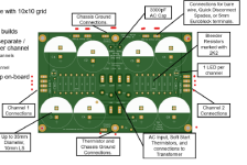
I am using Thatcher's power supply. TH1 is tied to Chassis GND.
So I diode checked with multimeter the chassis GNDs and all was OK. Problem is all the other connection (red dots below) also showed short to chassis GND ! ****... something bad wrong. Gunna tear it down again and see what's up.

The saga continues...any thoughts gang?

- Turned up on DB tester and bulb got bright and dimmed - nice
- Voltage seemed OK ~+/-26V - Using 20V Xformer - nice
- Smelled some hotness so turned off
- Scanned around with thermometer nothing obvious - no wire hotness as before as far as I could telll
- Turn back on and bulb dimed and then went bright again - not expected I think it should have stayed Dim - no?
- Tested voltages and got around 5-6V, smelled hotness and turned off
- Both LEDs did light - I did change the resistor to 1/2W during this effort
- Poked around with my finger and noticed TH1 was too hot in relation to other THx and resistors.
- Turned on again to get watts drawn and it was showing 50W and climbed to 65W before I turned it off.
I am using Thatcher's power supply. TH1 is tied to Chassis GND.
So I diode checked with multimeter the chassis GNDs and all was OK. Problem is all the other connection (red dots below) also showed short to chassis GND ! ****... something bad wrong. Gunna tear it down again and see what's up.
The saga continues...any thoughts gang?
Attachments
Don't know the amp did work aside from buzzing on occasion. I think I did something else wrong or something went bad (i.e. Cap, TH or Res.). Typical for me. I'll figure it out eventually... T
I would also look at the amp board that was connected to the hot crimp, pointing to a possible "leak" or mild short. If the crimp was adequate (which was my thought after seeing your weight on a crimped wire image), it points to that specific rail having a potential short (maybe just a 'mild' short). I had this happen on my F4 when I used washers to hold down the circuit board that were too wide and pressed with enough pressure on the solder mask to make a mild short, or leak. I say mild short because there was some resistance the solder mask was helping create, but it was pressed thin and my washer was creating a short to ground. The moment I just loosened the bolt on the washer, the resistance would jump from a couple ohms, back up to Megaohms. I, of course, just removed the washers for my fix.
Point is use a DMM and "poke around", with amp unplugged from power and caps fully drained, to see if you can find any shorts to ground where there shouldn't be. I use the schematic to find spots I know should have open (or very high Mohm resistance) to ground, then do a quick check with DMM.
Point is use a DMM and "poke around", with amp unplugged from power and caps fully drained, to see if you can find any shorts to ground where there shouldn't be. I use the schematic to find spots I know should have open (or very high Mohm resistance) to ground, then do a quick check with DMM.
I don't even have the amp boards connected yet just testing supply. Seems like everything on PS Bd shorts to Chassis GND. Think I have 1 or more shorted caps, don't see any solder jumpers or anything else odd. Gunna try and pop caps and test them, they might have been compromised from past issue(s).
Gotcha, well after you fix the PSU, definitely still hunt for any leaks/shorts on the amp boards with a DMM before powering up. Last thing you want is to fix the PSU only to have it fail again because the actual cause of failure was on the amp boards. God speed and good luck!
I look forward to seeing that you have it back up running hum free and learn what the issue was when you report back.
I look forward to seeing that you have it back up running hum free and learn what the issue was when you report back.
@tgrier -
For grins... Take any old electrolytic cap out of your stash. Put your meter set to resistance across the leads for about 10s. Watch the result... switch it quickly to DCV and watch the results. Flip it back to resistance. Switch the probe leads and do the same thing.
Your measurements likely do not indicate a short to GND. Read the actual resistance and report back. I am guessing (but no way to be certain) that you likely had your meter set to "continuity / beep mode" and just heard the beep.
TH1 being exceptionally hot indicates an issue. TH2 and TH3 should be hot.
Let us know how things progress. Good luck! You'll get it tackled.
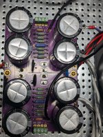
Tony - can you show a picture of the amp from overhead?
Can you describe how you confirmed the transformer wiring pairs on primary and secondary side?
As Patrick states above, I can confirm that TH1 heating up indicates a fault. TH2 and TH3 will be hot when powered up, that is perfectly normal.
Can you describe how you confirmed the transformer wiring pairs on primary and secondary side?
As Patrick states above, I can confirm that TH1 heating up indicates a fault. TH2 and TH3 will be hot when powered up, that is perfectly normal.
All I have is what is above post re-wiring without crimp connectors. I used Antek spec sheet and the way I had wired up before getting rid of crimps.
Primary Blue/Green to Bridges AC connections
Black/White from rectifiers +/- to +/- From Diode Bridge on board
Red/Black to 0A/B from Primary and 120A/B
Thanks T
Here's were I'm at now:

Primary Blue/Green to Bridges AC connections
Black/White from rectifiers +/- to +/- From Diode Bridge on board
Red/Black to 0A/B from Primary and 120A/B
Thanks T
Here's were I'm at now:
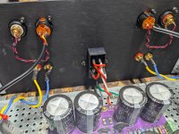
I can't quite tell in the pix which bridges you have - but I'm going to drop a fresh pair with a plastic cases + the new rectifier boards in the mail to you. There is a possibility you have a short to ground through the bridge board to the chassis. The new board has 2 ways to prevent that from happening: no bottom traces + a big screw hole.
Since your amp is in a disconnected state now it's easy enough to measure to see if this is a problem. Can you measure resistance between the chassis floor and the rectifier bridge connections. What do you get?
Since your amp is in a disconnected state now it's easy enough to measure to see if this is a problem. Can you measure resistance between the chassis floor and the rectifier bridge connections. What do you get?
Try this^^Since your amp is in a disconnected state now it's easy enough to measure to see if this is a problem. Can you measure resistance between the chassis floor and the rectifier bridge connections. What do you get?
I can't quite tell in the pix which bridges you have - but I'm going to drop a fresh pair with a plastic cases + the new rectifier boards in the mail to you. There is a possibility you have a short to ground through the bridge board to the chassis. The new board has 2 ways to prevent that from happening: no bottom traces + a big screw hole.
Humm, getting a short on + ( 0.1ohm) side of one of the bridges. The rest show OL. Bridge case shows short to Chassis GND.Since your amp is in a disconnected state now it's easy enough to measure to see if this is a problem. Can you measure resistance between the chassis floor and the rectifier bridge connections. What do you get?
- Home
- Amplifiers
- Pass Labs
- Aleph Jzm