I tried increasing r4 on both halves from 221k to 2x221k did not work.
Worth decreasing R1 to 10k ?
Worth decreasing R1 to 10k ?
In my understanding (perhaps flawed 😀) gain is set by a combination of feedback resistor,input resistor & resistor to ground.I rechecked their values and they are proper.
Increasing feedback resistor,decreasing input resistor (whatever I do) gives me additional 1VAC gain.
I must have done something wrong. Any other parts of the circuit that affects gain
Increasing feedback resistor,decreasing input resistor (whatever I do) gives me additional 1VAC gain.
I must have done something wrong. Any other parts of the circuit that affects gain
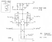
ref. to original Pa's circuit , ratio of R4/R1 is defining CLG of amp
that's 221K/22K1
you can freely ignore R2 (221K) from that
that's 221K/22K1
you can freely ignore R2 (221K) from that
Problem resolved...
I had explicitly grounded the daughter board to PSU.
I was trying out ARTA & it gave me a THD of 0.48% at 2.8V.
Generally I was unhappy 😀
As part of fiddling process the ground wire came loose & to my surprise the THD dropped to .038%.
Whipped out my multimeter
Relative DC 12mV
Absolute DC -130mV
Gain 20dB
ARCHIMEDES MOMENT
Arta measurements attached
Attachments
Last edited:
Hi Everyone,
I'd like to build the AX-J, and have Peter's boards. Is it possible to build with the following specs and parts. I have used the A-X v2 spread sheet, but would like to ask the experts if I'm doing something wrong.
Transformers are 14.25v secondary volts at 267VA. Basically building around these transformers because I have several. They are Amveco toroids and look well made. 130C, potted centers and thermal protection.
From spreadsheet:
Rectified voltage is ~20VDC
19v at mosfets. .55A per mosfets.
8 mosfets per channel.
8 ohm is 24W output.
Spread sheet says Factor 3 is 251W. Factor 1 is 167W. Not sure what "factor" means.
Dissipation per channel 84W
Dissipation stereo 167W
Is the 20 volts provided too low?
I'd be willing to lower the current through the mosfets, if it helps.
Thanks,
Vince
wow, I was not aware of any of Peter's boards still being around. I gave up the idea of converting my PD Aleph30 to AJ and started planning on building F4s instead w/ a tbd preamp (probably BA-3 FE). still, if I had AJ boards I might be tempted to try a quick conversion over the same footprint on the heatsinks.
Late to Aleph J-X party
Being very late to read about the Aleph J-X it seems. Built BBA3 and BA-1 SE as well as Aleph J's. Now very interested to upgrade my J's (which are fantastic, and measure very well with Arta as well) to get some more power (I have 86 dB/1W speakers)
Option 1: Turbocharge the J's by going from 4 to 6 output FETs, and run total bias of say 1,33x3 =4 A bias @ 27 volts (36 W/FET), giving around 40 watts RMS output with better handling of low speaker impedance (than stock AJ)
Option 2: Build Aleph J-X, easily getting 100W (bias/channel 1,4x6=8,4 amps @22 volts - know the thermal stuff will work out since I run at 9 Amps already in the same box @22 volts
Option3: Realise the sound level increase will be limited => do nothing and just enjoy the music.
Any advice from the experienced builders here on what route to prefer?
Also asking is anyone has Peter's input boards for sale (so Option 2 is kind of interesting still 🙂 🙂)
Thanks!!!
option ZM - buy more sensitive and more efficient speakers
option 1 - with 8R speakers , Iq (thus max I) isn't limiting factor , but rails voltage is ; so, no go
option 2 - some thoughts in Babelfish XJ , or JX …….. or whatever (Aleph X servo for Greedy Boyz)
option 1 - with 8R speakers , Iq (thus max I) isn't limiting factor , but rails voltage is ; so, no go
option 2 - some thoughts in Babelfish XJ , or JX …….. or whatever (Aleph X servo for Greedy Boyz)
Thanks ZM for quick reply.
Agree on option 1, rails voltage is limiting (speakers are pretty flat at 8 ohms except a dip to 3 ohms at 3 kHz (with little need of power at that frequency), so need more volts).
Well, option ZM is of course possible, but I don't think I can abandon my electrostatic QUADs never
Agree on option 1, rails voltage is limiting (speakers are pretty flat at 8 ohms except a dip to 3 ohms at 3 kHz (with little need of power at that frequency), so need more volts).
Well, option ZM is of course possible, but I don't think I can abandon my electrostatic QUADs never
whatever route you go , searching for more power is ..... more power 🙂
then go with small XJ , 5 per quadrant
200W of heat per channel will give you 65W/8R and 40W/4R
in any case - that means new amp ........
perfect excuse to start making two monoblocks 🙂
then go with small XJ , 5 per quadrant
200W of heat per channel will give you 65W/8R and 40W/4R
in any case - that means new amp ........
perfect excuse to start making two monoblocks 🙂
Thanks again ZM,
Yes, A X-J seems like the fun way to go...seeing(rather hearing) what SuSy can bring to an already very sweet-sounding design, the Aleph J.
Just one question. Why do you recommend 5Q/quadrant?
I can see of course see (potentially) long term reliability as an advantage.
The reason I ask is that i see much lower distorsion and nicer behaviour in my AJ when i increase bias (1W 8 ohm) 0,85A - 0,052%, 1,05A - 0,039%, 1,25A - 0,031% (and lower distorsion all the way up to 25 watts). 6L6 has documented the same thing in the AJ build thread. Bias and heat is good...🙂
My 40 kilo mono block boxes can handle around 9 Amps @23V rails for a X-config (52 degrees on top of fins -- facts from my bridged BBA3 + BA-1 build).
So why not use 3Q/quadrant, each Q biased at 1,5A (approx 33 watts/Q , and if using Keratherm and really the big sinks it should be safe )
instead of
5Q/quadrant, each Q biased at 900 mA (approx 20W/Q).
From spectral analysis, the 3/quadrant would behave much better, from the
First Watt until clipping...
What am I missing? 😱 (other than sound is what counts, not spectral analysis)😀
sum Iq is what counts , not exactly Iq per part , at least from point where you have enough volts and (mili)Amperes per one
number of outputs/pairs is a matter of choice - heat spreading across heatsink , availability of matched sets etc.
as I wrote several times (mostly in Babelfish J thread) , I prefer IRFP150 to IRFP240 in most cases , due to fact that one 150 is practically two of 240 , so it is more practical in several scenarios
so - having 3 per quadrant or having 6 per quadrant is matter of (your) choice , while primarily important thing is that you have enough Iq , and rail voltage is much less critical ...... simply because we are going bridged
If I use dual 15v secondary transformers...
Much appreciated if I (a newbie who built myRef and VFET by straightly following build guides) may get some help on a potential build of JX.
I have gathered the following parts so far:
-Peter's pcb;
-2 matched pairs of J74 BL; and
-some 20 IRPF240 (not yet matched).
Q1: I happen to have 2 piltron 300VA transformers with dual 15v secondary. I don't want to spend money for 18v secondary transformers. Do the resistor values need to be adjusted for a lower rail voltage? I seem to read somewhere that R8, R25 & R26 etc. need to be adjusted. I am happy with a low wattage (say 15W) amp.
Q2: Is my understanding correct that each channel requires a matched pair of J74?
Thanks!
Attachments
Thanks Zen Mod for the speedy reply!
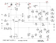
I am trying develop a better understanding on the circuit and came across the attached schematic for "wimpy +/-12V PSU" you posted at post #36 of thread titled "Low watt Aleph J".
Low watt Aleph J
If you don't mind to share with me, what is the purpose of modifying the values R8, R25, R26 & C4, using the green LED and connecting R4 to OUT??😕
Thanks again!🙂
Attachments
Last edited:
above input LTP - that's "just" iteration of CCS for LTP
rest is accomodation of values for substancialy lowered rails
R4 is feedback resistor ........ I believe it was correction of some previous mistake in schmtc ...... here drawn as it need to be
rest is accomodation of values for substancialy lowered rails
R4 is feedback resistor ........ I believe it was correction of some previous mistake in schmtc ...... here drawn as it need to be
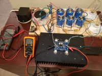
I am bringing this thread back from the dead. After way too many years of collecting parts to build a Pass clone I finally put power on one channel of my Aleph J.
There was no magic smoke so it looks like I put it together correctly. The DC offset started at 92mV and dropped to 72mV after 30 minutes. The heatsink warmed up to 120 degrees Fahrenheit. The PSU is a test PSU that I put together, the light bulbs (100W) were used to test the PSU. I got +-24V when testing with the bulbs. With the one channel powered I am getting +-22.9V. The transformer is a 2 x x18V 600VA Antek, capacitors are 68,000uF / 50V.
The second channel is already assembled, I just need to put it on it's heatsink. I still need to order the material to finish building the chassis.
Next I need to see if this will actually produce sound.
I have 3 other Class A projects in the pipeline.
Attachments
- Home
- Amplifiers
- Pass Labs
- Aleph J-X Amp Project