That will be fine, depending on your bias. Are you planning to use that for each channel or both? What did you decide on for your bias target? Use a transformer rated for at least double the bias VA figure.
Last edited:
Not sure where you are planning to put the LED, but if in place of the fuse, all the line current will want to go through it.
A fuse in the mains at the IEC is plenty. The soft start just includes it to be sure that there is one. Eliminate the soft start fuse and everything will be fine.
However, even with a soft start, you will want to go higher than 2A. What is your idle dissipation in the amp? Add losses in the transformer, rectifier and inductor and you've got to be able to handle that continuously. Divide by your mains voltage (220?) and you've got the current assuming a perfectly resistive load, which it isn't. A less than perfect power factor will make you line current higher. Add a but more capability.
The other consideration is inrush current. Even with the soft start you could effectively have just over 40R across the mains. That's a 55A surge at 220V. A 2A fast blow fuse probably won't cut it.
I use a CL60 for inrush current limiting in an amp with a 1KVA toroid and 90,000 uf on US 120V mains. It took a 10A fast blow fuse to handle the inrush, and even that blew every few weeks on startup. I finally settled on a 6A slow blow fuse that seems reasonable on an amp that draws 3.5A.
That's a long winded way of saying some experimenting might be in order to find the appropriate mains fuse. 😉
BTW, it's safer to run your pilot LED off the transformer secondary - one less opportunity for the mains to short to the chassis. If you run it off AC, have a standard diode connected the opposite polarity to limit the reverse voltage the LED sees. Size the current limiting series resistor to get the LED current you want. R=(V-Vf)/I Where V is the voltage you are using to drive the LED, Vf is the forward voltage drop of the LED and I is the chosen current. If you are using AC to drive it, remember that the standard diode only has a Vf around .6V when calculating the resistor dissipation.
Last edited:
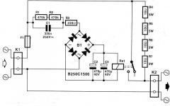
Thanks again. I add in a LED to be sure there's power going into the amp...I'll incorporate a CL60 but this is before the soft start circuit, right?
Walter, that's a different circuit from elektra, right?
Walter, that's a different circuit from elektra, right?
Last edited:
The CL60 is instead of the soft start. It's resistance starts relatively high and then as it heats up it drops. Some say they should be bypassed anyway, in which case you could put it in place of the resistor(s) in your soft start.
Chances of a transformer failure are small. An LED from rail to rail or rail to ground would be a good power on indicator. You can connect to the rails right after the bridge or anywhere down the line.
Chances of a transformer failure are small. An LED from rail to rail or rail to ground would be a good power on indicator. You can connect to the rails right after the bridge or anywhere down the line.

Hi Bob,
which means i replace the 10R resistors (5nos) with one CL60? My current amp uses a CL60 but it isn't that effective....i can see my speaker cone moves out and in when powering up or turning off my amp. I'll bypass the LED if it's too troublesome. The only reason I want it at the soft start is to make sure that there is current at the socket before it reaches the PSU.
I have 220R instead of 221, 22k instead of 22.1k, 68k instead of 68.2k, 3.3k instead of 3.32k, 390 instead of 392R and 4.7k instead of 4.75k. Are these value critical? I have .47 3w metal oxide resistors, can these be use?
Thanks.
Hi Walter, what value of resistor and zener did you put in after the capacitor? Thanks.
Last edited:
That's a little different issue than soft start. The CL60 or soft start limits the inrush of current to empty capacitors and a large transformer's magnetizing current.
Speaker thump is caused by the amp itself. DC offset changes as the operating point changes, causing the thump. You could prevent that with a relay in the speaker leads that closes after a suitable time delay.
All your parts are within 1% tolerance. A 220R resistor is less than 1% away from 221R and so on. Don't sweat it. That's the beauty of Papa's designs published here, very few values are critical except device matching.
Your 3W resistors should be fine. To make yourself more comfortable, calculate the dissipation. Mount them a little up from the board so some air can circulate and keep them cool.
Thanks again, Bob, appreciate your help. All the resistors are at 1/4 w, correct? I couldn't find the aleph j service manual, any one can help?
Last edited:
Yes, but some will go to 1/2W. The idea is that you get less thermal effects with resistors capable of higher power dissipation. Will you hear the difference? Is it worth a few cents a resistor to find out?
Which do you suggest putting a 1/2 w? What is the value of Z1 (zener)? Is there an alternative to ztx450? these are hard to find, at least in my area.
- Home
- Amplifiers
- Pass Labs
- Aleph J-X Amp Project