hi all
whats the best caps to use in the following positions if money is no object
c1
c2 and c3
c4
c5
cheers
whats the best caps to use in the following positions if money is no object
c1
c2 and c3
c4
c5
cheers
hi all
whats the best caps to use in the following positions if money is no object
c1
c2 and c3
c4
c5
cheers
Your gonna regret that statement😀
hi luke
my wallet already does
but i,m planning on this amp being my final and ultimate diy build so i,m using the best of everything and any way whats the worst it can get ,ive already priced some vcaps for c1 at $275 each !
my wallet already does
but i,m planning on this amp being my final and ultimate diy build so i,m using the best of everything and any way whats the worst it can get ,ive already priced some vcaps for c1 at $275 each !
hi luke
my wallet already does
but i,m planning on this amp being my final and ultimate diy build so i,m using the best of everything and any way whats the worst it can get ,ive already priced some vcaps for c1 at $275 each !
Hi slr (5 bil...),
are you single?


To me no cap will ever be worth $275, Ive built amps for less.
IME theres no such thing as a final and ultimate DIY build, and your tastes may change too.
You may hear something one day and say thats what I want and have to do a complete rethink;-)
BTW SLR5000 who pays your gas bill😀 I hear ford will discontinue the Falcon in teh coming years, who will compete with Holden at Bathurst?
their on to us euvl
they have been following this thread and have put up the price
i paid $6.99 just a day or so ago 😕
hi ma_coule married with 2 sons but i have a hidden bank account for my diy😀
hi luke
i hope your not trying to start a ford vrs holden thing here 😉
the slr is just a weekend car so no major juice bills
hi all
whats the best caps to use in the following positions if money is no object
c1
c2 and c3
c4
c5
cheers
C1 and C5 can be replaced with jumpers, if you really need C5, use twisted wire. For other 3 caps I would use Black Gate N type.
Hi All
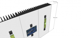
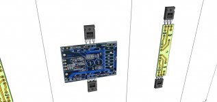
I intend to build the aleph J-X version with 12 mosfets per channel. Attached is the heat sink size. I am using Peter's board and I think extenting the mosfet out will be better. The heat sink size is 300H x 130w x 50d. Are these heat sink good enough? These are the best that I can find here.
I intend to build the aleph J-X version with 12 mosfets per channel. Attached is the heat sink size. I am using Peter's board and I think extenting the mosfet out will be better. The heat sink size is 300H x 130w x 50d. Are these heat sink good enough? These are the best that I can find here.
Attachments
i did an aleph 5 with 2 rectifier on almost half of the size of this heat sink and it extremely hot..😡....this is why the overly size heat sink for the rectifier😱
Well, if you are speaking from experience, I stand corrected. 😀
I have a pair of F-4's running and using 4 independent devices instead of a rectifier block, I don't run any sinking and have no heat issues. I know my F-4's aren't likely pulling as much juice, but that seems like a lot of heat. Would a higher efficiency rectifier produce less heat?
I have a pair of F-4's running and using 4 independent devices instead of a rectifier block, I don't run any sinking and have no heat issues. I know my F-4's aren't likely pulling as much juice, but that seems like a lot of heat. Would a higher efficiency rectifier produce less heat?
Should I also move the gate resistor to the extension board?
The gate stopper resistor should be as close to the devices as possible. The idea is to have it between any inductive leads and the capacitive gate to prevent resonances. Breaking the trace on the extension boards wouldn't be a bad idea.
aleph j-x
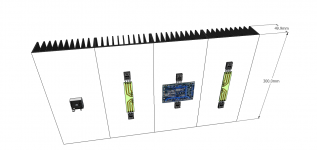
Hi, thanks. Would it be better to move the Source resistor to the extension board as well? I have seen many people done this. Can the heatsink be reduce to 250mm height and still able to cope with the heat? Also, I like to incorporate a soft start to the PSU. The attached scheme is stolen from somewhere in the post. Is this soft start OK for the PSU?


Hi, thanks. Would it be better to move the Source resistor to the extension board as well? I have seen many people done this. Can the heatsink be reduce to 250mm height and still able to cope with the heat? Also, I like to incorporate a soft start to the PSU. The attached scheme is stolen from somewhere in the post. Is this soft start OK for the PSU?
Attachments
Last edited:
... Also, I like to incorporate a soft start to the PSU. The attached scheme is stolen from somewhere in the post. Is this soft start OK for the PSU?
My Aleph-J is running with exactly that softstarter - go for it.
(Circuit's origin is a mag called ELEKTOR - you may have seen it mentioned around here and on BAF)
Would a higher efficiency rectifier produce less heat?
Hi Dave
I wouldn't know. I did not change it though a member have suggested the Stcoky rectifier, which is much more expensive.
Thanks vrun. I am now looking for some PSU scheme.
The location of the source resistor isn't as important as the gate stopper. Place it wherever is convenient, allowing a bit of space for air circulation.
The critical number for heat is the device junction temperature. Shoot for <100C for reliability.
The thermal resistances you need to concern yourself with are:
R(jc) Junction to case
R case to isolator
R isolator to sink
R sink to air
R(jc) is from the device data sheets, the R across the isolator usually ends up somewhere around .7 C/W, and the Sink to air is from the data sheet. Adjust the sink R to account for the length if other than specified (often spec'd at 3", doubling the length usually gives around a 33% reduction in resistance) Adjust for sink temp lower than the test condition specified.
Multiply the thermal resistance sink-air by the power dissipated on the sink. If this rise is under 30C, you are OK and your sinks will stay below the 55C target (won't burn anyone who accidentally touches them)
Add up all the thermal resistances, multiply by the power dissipated on the sink. This will be the junction temperature rise above ambient. Add 25C (nominal room temp) and verify the number is under 100C. If so you are good to go, if not, bigger sinks, lower bias or more output devices are required.
Post your calculations and we can sanity check them.
Hi and thanks...
I have found this link : Heat Sink Temperature Calculator
From IRFP240 data:
Maximum Ambient Temperature.................30 (°C)
Maximum Junction Temperature...............150(°C)
Thermal Resistance - Junction to Case.....0.83(°C/Watt)
Thermal Resistance 1............................do not know(°C/Watt)
I do not know the thermal resistance of the heat sink..
Power.....100w(?) for aleph j-x?
Junction Temperature??(°C)
If i do not put in the value for the thermal resistance, I got a junction temperature of 113 °C. Very confusing
thanks
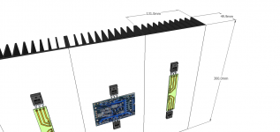
Look around suppliers to find an extrusion that matches yours reasonable closely. Based on your sketch, let's use .this profile. M&M doesn't give too much information about how they calculate Rtheta, but at 1.3C/W/3" It's probably safe to assume that at 250mm tall the net Rtheta for the section is .5-.6°C/W.
What bias did you plan to use? If idling at 100W as you mentioned, then you are looking at 50W per section. That will give you 25-30°C rise above ambient. This leaves the sinks at NP approved 50-55°C. So far so good.
With two output devices per sink, you have 25 W per device. Assume your isolator adds .7°C/W and your device is.83°C/W junction to case. Add up the Rs to 1.53 multiply by 25 W and you've got another 38C rise above heat sink temperature, a comfortable 88°C at the junction.
If you were planning 12 output devices and shooting for 100W output, then you probably ought to use the 300mm long sections or monoblocks with 4-6 sections per amp for the outputs.
HTH
Last edited:
- Home
- Amplifiers
- Pass Labs
- Aleph J-X Amp Project