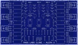
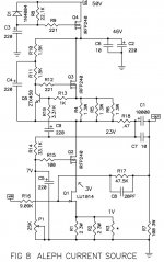
I know where I picked up the term CCS with repect to the IRFP240(s) and the Aleph, it is on the Aleph X pcb at www.kk-pcb.com/aleph-x , one half of the MOSFET IRFP240(s) is noted CCS(constant current source), is this wrong ? I will re-read more papers, but something I am not shure about is should we be using IRFP240(s) & IRFP9240(s) in the power supply to create a constant current source as done in the power supply given in Zen Variations Part 5 page #7, or are there IRFP240(s) on the AJ-X pcb perform this task as seen in the Aleph-X pcb www.kk-pcb.com/aleph-x ?Yes I have studied all of the Pass Projects, some of them I should read again. When you said "it uses Aleph dynamic current sources", is this similar to the "modulated supply for a Zen Amp" Page3 Zen Variations Part3 ? I know it is in 'Zen Variations Part9' I was not thinking when I said "CCS", I meant IRFP240(s)used for its modulating power supply, I think this is correct,is it? I have been thinking of it as being a CCS power supply that modulates, I know it dose not make sence because a CCS dose not modulat, I will begin to think of it in its own way of working without thinking of CCS first, I dont know why I have been doing that.
Thanks for pointing that out so I will look over the Pass Projects again now that I have a better understanding of what I am doing, I will probibly make more errors but I have been trying, but I have not been thinking clearly lately.
I hope this is not a stupid question, I know that I tend to ask alot of stupid questions?
Attachments


SCAIFF001
In an Aleph or Aleph-X there are active current sources. These are mislabeled on the KK boards as Constant Current Sources. The active current source is similar to a CCS, except that it is modulated by a portion of signal.
Read up on Constant Current Sources and Constant Voltage Sources. You might spot the difference of purpose between the active current sources and the purpose of the IRFP240/9240 in the power supply schematic.
You can also model what happens to the current and voltage as you load the ACS and PSU with different resistors. You'll see that they perform vastly different functions.
mislabeled kk boards
Thank you for varifying for me that the kk boards are mislabeled because it has been the main root of my percieved lack of knowlage about the operation of the Aleph amplifiers, currently I have the Aleph J-X pcb(s) and 2SJ74(s), now I can order the other parts, for the Aleph J-X with a peace of mind that I did not have untill this CCS issue has been resolved on the kk pcb(s).
SCAIFF001
In an Aleph or Aleph-X there are active current sources. These are mislabeled on the KK boards as Constant Current Sources. The active current source is similar to a CCS, except that it is modulated by a portion of signal.
Read up on Constant Current Sources and Constant Voltage Sources. You might spot the difference of purpose between the active current sources and the purpose of the IRFP240/9240 in the power supply schematic.
You can also model what happens to the current and voltage as you load the ACS and PSU with different resistors. You'll see that they perform vastly different functions.
Thank you for varifying for me that the kk boards are mislabeled because it has been the main root of my percieved lack of knowlage about the operation of the Aleph amplifiers, currently I have the Aleph J-X pcb(s) and 2SJ74(s), now I can order the other parts, for the Aleph J-X with a peace of mind that I did not have untill this CCS issue has been resolved on the kk pcb(s).
Attachments
I was hoping to lead you along the path to discovering that the PSU uses the mosfets as a constant voltage source. Simulate the response to various loads and you'll see the current changes but within reason the output voltage remains constant. There is no feedback, so it is akin to a capacitance multiplier, and will have quieter output than the capacitor output supply that feeds it.
I have not ordered parts yet so I can still do some thinking, can I really use the MOSFETs in the psu of the Aleph J-X, because my understanding of the modulating power supply the input to the output power MOSFETs are linked to the input of the constant current source MOSFETs via resistors and capacitors, and this is the setup of the Aleph power supply. Can I still add power supply MOSFETs,as in Zen Variation Part5 pg7 to the Aleph amplifier without distroying what is being accomplished without them?I was hoping to lead you along the path to discovering that the PSU uses the mosfets as a constant voltage source. Simulate the response to various loads and you'll see the current changes but within reason the output voltage remains constant. There is no feedback, so it is akin to a capacitance multiplier, and will have quieter output than the capacitor output supply that feeds it.
I am holding back ordering the parts untill I come up with an answer, maybe I should order the extra MOSFETs and build both power supplies to see which is the best way to approach this problem, the extra cost will be small for four 240s & 9240s.
I am still learning but would like to build this amplifier before I know everything about it because that might take to long, so I need some helpfull directions because I seem to be second guessing myself all of the time now and dont know which way to go.
Thank You for your help.
Attachments
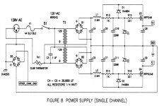
The actions of the power supply are completely independent of the active current sources in the AJ-X. What the mosfets do is provide quieter more stable voltage than might otherwise be provided by a CLC or CRC PSU.
Keep in mind the current you plan to pass through the regulators and power dissipation of Q3 and Q4. You may find that you want to parallel matched pairs (with 0r33 emitter resistors to encourage more even load sharing.) They will need to be mounted to significant heat sinks. There will be a minimum of ~4V across Q3/4, most likely 5-6 or more. If you bias at only 5 amps you'll be dumping 25-30W. Be sure to add that dissipation into your heat sink size calculations if you mount them to the output device sinks.
You can omit R13, R14 and everything to the right of them and take your rails from the junctions of L1/C6 and L2/C7 if you like and have a perfectly usable power supply. The regulator section may be overkill, but that's why most of us DIY - to get overkill that may not be commercially viable.
HTH
dose it make a differance in sound using expensive components
Dose anyone know if it makes a differance using silver-gold Mundorf wire HGC pure silver wire, Audio Note internal tonearm wire, Mundorf silver/gold wire, cardas cartridge clips, PTFE sleeving, heatshrink, silk tubing, cotton tubing, Audio Note speaker cable, OFC loudspeaker wire or Mundorf electrolytic capacitors Mundorf Mlytic® Audio Grade electrolytic homepage or Nichicon electrolytic capacitors Nichicon KG type electrolytic capacitors homepage or Nichicon KG Type electrolytic capacitors http://www.hificollective.co.uk/pdf/nichicon_kg.pdf
Dose anyone know if it actually makes an audible differance in sound before I purchase, because I would like to make it the best sounding without waisting money because I am medically disabled so I dont have allot of money, but I still love the sound of my favorate music on my stereo?
Thank You for your help.
I have no direct experience with most of the items mentioned, but I suspect that you'll be very far up the diminishing returns curve if they do make a difference. Is the rest of your system up to that level of resolution where you might notice a fraction of a percent improvement? Source, DAC, Speakers (most important IMHO)?
Want to try silver plated ptfe insulated wire at reasonable prices? Visit forum sponsor www.apexjr.com Steve is a reliable vendor with great prices. He's received a good portion of my discretionary income over the years, always service with a smile and I've never had a problem. Just a satisfied customer, no relation. He also has heat sinks, PSU caps, transformers...
Want to try silver plated ptfe insulated wire at reasonable prices? Visit forum sponsor www.apexjr.com Steve is a reliable vendor with great prices. He's received a good portion of my discretionary income over the years, always service with a smile and I've never had a problem. Just a satisfied customer, no relation. He also has heat sinks, PSU caps, transformers...
The actions of the power supply are completely independent of the active current sources in the AJ-X. What the mosfets do is provide quieter more stable voltage than might otherwise be provided by a CLC or CRC PSU.
Keep in mind the current you plan to pass through the regulators and power dissipation of Q3 and Q4. You may find that you want to parallel matched pairs (with 0r33 emitter resistors to encourage more even load sharing.) They will need to be mounted to significant heat sinks. There will be a minimum of ~4V across Q3/4, most likely 5-6 or more. If you bias at only 5 amps you'll be dumping 25-30W. Be sure to add that dissipation into your heat sink size calculations if you mount them to the output device sinks.
You can omit R13, R14 and everything to the right of them and take your rails from the junctions of L1/C6 and L2/C7 if you like and have a perfectly usable power supply. The regulator section may be overkill, but that's why most of us DIY - to get overkill that may not be commercially viable.
HTH
Thank You for your reply, I will be parallelling Q3&Q4, so I might be useing up 4volts per MOSFET, so I will have to get a transformer 25volts to have 25volt rails with this modification along with the choke, dose this sound right to everyone ?
I believe that the best power supply will be a modulated constant current source, where would I connect the Q3 & Q4 MOSFET Gate(s), in Zen Var.Part5 pg7, to the Aleph Amp output, and would I use the value for the resistor and capacitor linking the power supply MOFET Gate(s) to the Zen Amp output MOSFET Drain ? I might be in over my head now, I need some communication on this modulating CCS power supply, Zen Var.Part3 Page3.
Thank You for your continuing help everyone.
Attachments

hi all
just want to let you know that littlediode.com in the uk still has the 2sj109
if you need any
they are $6.99 eu each
cheers
just want to let you know that littlediode.com in the uk still has the 2sj109
if you need any
they are $6.99 eu each
cheers
Hi Classafanatic,
What group of Idss they have, BL, V?
Thanks
Prakit
What group of Idss they have, BL, V?
Thanks
Prakit
hi all
just want to let you know that littlediode.com in the uk still has the 2sj109
if you need any
they are $6.99 eu each
cheers
Hi,Hi Classafanatic,
What group of Idss they have, BL, V?
Thanks
Prakit
here are mines, from the same supplier.
Any comment?

Attachments
Hi,
I always wondered what Idss group of the Jfet they have for sale since the web didn't give detail about it.
Considering the now-higher price for a matched pair of J74, with an EUVL's heatsink, the price for a J109 at 6.99 Euro seems reasonable. The weaker Euro makes this attractive too.
Thanks again for sharing the info.
Bests
Prakit
thats great
when did you buy them and did you specify bl or is that just what they sent you
cheers
when did you buy them and did you specify bl or is that just what they sent you
cheers
Hi,thats great
when did you buy them and did you specify bl or is that just what they sent you
cheers
Bought on: LittleDiode Ltd. in April 2010 as "2SJ109"
Thank You for your reply, I will be parallelling Q3&Q4, so I might be useing up 4volts per MOSFET, so I will have to get a transformer 25volts to have 25volt rails with this modification along with the choke, dose this sound right to everyone ?
I believe that the best power supply will be a modulated constant current source, where would I connect the Q3 & Q4 MOSFET Gate(s), in Zen Var.Part5 pg7, to the Aleph Amp output, and would I use the value for the resistor and capacitor linking the power supply MOFET Gate(s) to the Zen Amp output MOSFET Drain ? I might be in over my head now, I need some communication on this modulating CCS power supply, Zen Var.Part3 Page3.
Thank You for your continuing help everyone.
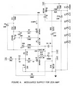
The supply you linked to is not a modulated current source, it is a modulated voltage source. Understand how it works in the ZV3 before you try implementing it in an AJ-X. You would hook it up as shown and change the resistor values to match.
The Zen V5 circuit has low ripple rejection, therefore needs the extra smoothing of that PSU, but the standard AJ-X is fine without it. You'll be burning an awful lot of energy for a marginal improvement if you regulate the rails.
A side note - if you use the ZV5 regulator and only drop 4 V then the Fets are full on and not doing anything for you except wasting energy. You want them dropping a bit more than Vgs - that's why I suggested 5-6V. Add a volt or three for the drops in the resistors and inductors preceding it, so a minimum of 25VAC to get 25VDC rails.
Have you looked at what size heat sinks you'll need for an x amp running 25 volt rails? What do you plan on for bias current? If 5A, you'll get 100W into 8R output, dissipating 375W per channel. You'll want at a bare minimum 800VA transformer per channel, for three output devices per quadrant you'll need better than .14 deg C/W heat sinks for the outputs and .08 deg C/W for the PSU if you use only two pairs for the regulator's rails. (more pairs of regulator pass transistors reduce the heat sink requirement)
Reading a little further in the same ZV-3 article:
See Zen V3 page 3 figure 6 for schematic
Are you sure that you want to bother with trying to modulate the supply?
A Bipolar Version for Son of Zen
We can also build this supply as bipolar. No, not with bipolar
transistors, but a supply with both plus and minus voltages for
those amplifiers preferring two rails. Figure 6 shows such a
version of this MOSFET follower supply applied to a 10 watt version of
the Son of Zen. The Son of Zen has a poor PSRR by itself, and relies
on the matching of its balanced halves for low noise. It much
Pass D.I.Y Project: Zen Variations - part 3 page 3
appreciates a quiet and stable supply, and previously we have only seen
it with "pi" filtering.
See Zen V3 page 3 figure 6 for schematic
We do not modulate this particular supply as it sources two halves of a
balanced channel which operated out of phase. The supply draw of this
circuit is truly constant at all times, a "zero sum game" for the circuit. By
contrast, the Zen has a constant draw averaged over time, and the
instantaneous draw from the supply reflects the output current of the
amplifier.
Are you sure that you want to bother with trying to modulate the supply?
Last edited:
- Home
- Amplifiers
- Pass Labs
- Aleph J-X Amp Project