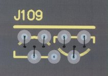
how should the 2sj74's be soldered to the board?
Check this post and the attached pic: http://www.diyaudio.com/forums/showpost.php?p=1855541&postcount=85
Attachments
Thanks Peter, I've missed this point. 😉
With 1.8A bias per side about 180 watts per ch.
do you think that 2 per channel of SK56/200SA http://www.fischerelektronik.de/fischer2002/_2002/pdf/einzel_pdf/A_42.pdf will do the job
I would like to mount them 2 on each side of the stereo box
do you think that 2 per channel of SK56/200SA http://www.fischerelektronik.de/fischer2002/_2002/pdf/einzel_pdf/A_42.pdf will do the job
I would like to mount them 2 on each side of the stereo box
I would use the SK157/ 150, two per ch.
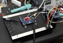
I tested a single Aleph J channel today and everything works fine.
300VA, 2 x 18V Plitron transformer produces approx 28V unloaded and 26V after connecting to the amp.
Loosely matched SJ74 give approX 35mV offset.
Next thing will be J-X setup.

300VA, 2 x 18V Plitron transformer produces approx 28V unloaded and 26V after connecting to the amp.
Loosely matched SJ74 give approX 35mV offset.
Next thing will be J-X setup.
Attachments
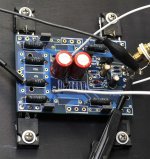
I wasn't actually correct, the DC offset was approx 2mV, I forgot about the offset produced by the generator.
The amp runs hot: the 8x8 heatsink with 1.75 fins was way too small for 2 x 18V transformer.
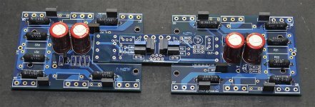
For AJ-X configuration, front end components (inside white border) should not be installed. I just removed them from test channel and I'm slowly getting ready for an X
The amp runs hot: the 8x8 heatsink with 1.75 fins was way too small for 2 x 18V transformer.
For AJ-X configuration, front end components (inside white border) should not be installed. I just removed them from test channel and I'm slowly getting ready for an X
Attachments
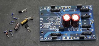
Resistor location on board
Hi Peter, thanks for the picture - very helpful! One more quick question. Why is R7 offset on your board - you soldered one leg to a different, unmarked thru-hole? Thanks!
-Alex
Hi Peter, thanks for the picture - very helpful! One more quick question. Why is R7 offset on your board - you soldered one leg to a different, unmarked thru-hole? Thanks!
-Alex
Peter,
What is the size of the thru holes you use for signal, ground, and power wires?
I am thinking of getting some turret terminals to facilitate quick solder/desolder for experimenting on mine.
Thanks,
Tom
What is the size of the thru holes you use for signal, ground, and power wires?
I am thinking of getting some turret terminals to facilitate quick solder/desolder for experimenting on mine.
Thanks,
Tom
Heatsink effectiveness vs. length
I am considering using 2 lengths of the barredboss's (Russ) new 10.25" heatsinks per mono J-X channel, with the daughter board spanning across them. I thought about getting 9" or even 12" lengths, but was wondering if the 4 Mosfets are distributed and centered across it, at what point does additional length become much less effective as it exceeds 6" high ... 9"? 12"? My trusty Conrads are 12"l x 6"h but the fins are not nearly as long, so I was hoping the deeper fins and added height would do the job.
The dimensions of these extrusions are:
.375" BASE THICKNESS
2.5" FIN HEIGHT
10.125" WIDE
2.875" TOTAL HEIGHT
.400 FIN SPACING C-C
24 TOTAL FINS
12.5 POUNDS PER FOOT
An externally hosted image should be here but it was not working when we last tested it.
I believe it is R-Theta that has an extrusion identical to Russ' extrusion. I did the calculations a while ago and two 6" pieces were ideal for a stereo J amp, so they would match an XJ monoblock perfectly.
Rule of thumb, when you double the length the capacity goes up about 50%.
For instance, if a 3" piece is .600 C/W, then a piece 6" long would be about .450 C/W.
Bill
Rule of thumb, when you double the length the capacity goes up about 50%.
For instance, if a 3" piece is .600 C/W, then a piece 6" long would be about .450 C/W.
Bill
Thanks very much for that tip. I didn't know there was a profile he was working from already, so I'll look through their site and try to locate the specs.I believe it is R-Theta that has an extrusion identical to Russ' extrusion. I did the calculations a while ago and two 6" pieces were ideal for a stereo J amp, so they would match an XJ monoblock perfectly.
Rule of thumb, when you double the length the capacity goes up about 50%.
For instance, if a 3" piece is .600 C/W, then a piece 6" long would be about .450 C/W.
Bill
Tom
I believe it is R-Theta that has an extrusion identical to Russ' extrusion. I did the calculations a while ago and two 6" pieces were ideal for a stereo J amp, so they would match an XJ monoblock perfectly.
Rule of thumb, when you double the length the capacity goes up about 50%.
For instance, if a 3" piece is .600 C/W, then a piece 6" long would be about .450 C/W.
Bill
would you please give an info about heatsinks you gonna use for your X - J (what rails and bias)
cheers
Peter,
In post 265 you have a picture of the board mounted to the heatsink. There is a blue item in the bachground which looks like a solder dispenser. I have never seen one of those. Could you perhaps let me know who makes it and maybe where to get one.
Tad
In post 265 you have a picture of the board mounted to the heatsink. There is a blue item in the bachground which looks like a solder dispenser. I have never seen one of those. Could you perhaps let me know who makes it and maybe where to get one.
Tad
Yes, it's solder dispenser, one of the most useful accessories I have, you can read more about it here: http://www.diyaudio.com/forums/showthread.php?t=3981&highlight=tools
would you please give an info about heatsinks you gonna use for your X - J (what rails and bias)
cheers
I have built two Aleph Js, one is standard design and one has three fets per rail. The standard design has a more organic sound than the higher powered one. I have no immediate plans to build an X amp, but if I did I would stick very closely to the Master's design for each half. 22-24V rails and .900A/fet bias.
Best, Bill
tms0425,
I have 4 of the barredboss 12+ inch heatsinks in one foot lengths. These are HUGE pieces of aluminum. I bought them from the initial lot before he removed the outer fins. Am I to believe that this little amp is going to generate that much heat? What lelvel of output will 22-26 volt rails yield in the j-x configuration. The j is like 30% efficient?
I am about to order the transformers and would like some input.
Maybe some fans might not be such a bad idea here.
Peter,
I Never got around to thanking you for the boards. Nice. Thanks I will be purchasing the solder thing this weekend.
Tad
Well, yes it should be plenty hottms0425,
I have 4 of the barredboss 12+ inch heatsinks in one foot lengths. These are HUGE pieces of aluminum. I bought them from the initial lot before he removed the outer fins. Am I to believe that this little amp is going to generate that much heat? What lelvel of output will 22-26 volt rails yield in the j-x configuration. The j is like 30% efficient?
I am about to order the transformers and would like some input.
Maybe some fans might not be such a bad idea here.
Peter,
I Never got around to thanking you for the boards. Nice. Thanks I will be purchasing the solder thing this weekend.
Tad
 . It's more so than the F4 and F5 since I believe you're looking at about 1.8A bias with 4 devices on the same rails.
- Home
- Amplifiers
- Pass Labs
- Aleph J-X Amp Project