I did a lot more digging last night and today and I found some of my answers.
RS (output to sources) = 10k or 22k
RG (output to ground) = Min. 33R 3W to 5W for 4 Mosfets
High output Euvl uses 100R
100W Caddock TO247s.
Now with respect to the "Premium" components are there any suggestions as to what would benifit the upgrade and what I should not bother with. I have read that carbon resistors shift (as I would expect all types do) and I should not use them in a position that would be used to hold a bias. I am lost on that part but hope to sort it out with some help.
James
"The additional mosfet pair is for people who need more power; it's only an option but since the board size allowed it, why not keep it?"
I thought these jfets can load max two pairs of Mosfets .
For more Mosfets we (2x3) have to cascade jfets, dont we? javascript:smilie('😕')
Christian
I thought these jfets can load max two pairs of Mosfets .
For more Mosfets we (2x3) have to cascade jfets, dont we? javascript:smilie('😕')
Christian
2SJ109GR
I found a pair of 2SJ209GR's *maybe fakes*... but I couldn't resist.
I was wondering with the lower ma output of the GR's be a problem here? I am assuming the circuit is designed for BL's and that if there is a tweak to use these critters or not.
😕
I found a pair of 2SJ209GR's *maybe fakes*... but I couldn't resist.
I was wondering with the lower ma output of the GR's be a problem here? I am assuming the circuit is designed for BL's and that if there is a tweak to use these critters or not.
😕
what heatsink Is propriate for a channel of Aleph J and Aleph JX
are conrad MF 35 150 fine
how about Fischer SK56/200 SA 0.3 C / W
how about toroid
are conrad MF 35 150 fine
how about Fischer SK56/200 SA 0.3 C / W
how about toroid
Hi Peter,
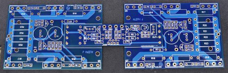
the pcb´s have arrived, thanks. Great material, I'm curious about the sound.
Regards Tom
the pcb´s have arrived, thanks. Great material, I'm curious about the sound.
Regards Tom
I matched up 2sj74 jfets.
I have a set of 4 with Idss of 7.4 mA and a set of 4 with Idss of 9.2mA.
Given that each device is biased around 4mA each would it be best to use 7.4mA Idss matched pairs or the 9.2mA Idss matched pairs, or is it much of a muchness?
I have a set of 4 with Idss of 7.4 mA and a set of 4 with Idss of 9.2mA.
Given that each device is biased around 4mA each would it be best to use 7.4mA Idss matched pairs or the 9.2mA Idss matched pairs, or is it much of a muchness?
Last edited:
It could, if it was enough space. You may still manage to drill some holes, if really needed.
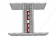
However, why complicate things, when the the X-Daughter board mounts directly into the pads on the two output boards (using pieces of wire)
Previously, there were complains that the boards were too small, now we have a single, full size assembly 😉
However, why complicate things, when the the X-Daughter board mounts directly into the pads on the two output boards (using pieces of wire)
Previously, there were complains that the boards were too small, now we have a single, full size assembly 😉
Attachments
I'm receiving some questions about X amp concept and advantage. Maybe those articles provide more info:
http://passlabs.com/pdf/articles/xa_paper.pdf
http://passlabs.com/pdf/product_lit/x_5-xa_5-amps.pdf
http://passlabs.com/pdf/articles/xa_paper.pdf
http://passlabs.com/pdf/product_lit/x_5-xa_5-amps.pdf
Does anybody know the best way to mount the daughter board for X configuration? There are no mounting holes?
I used cut-off wires from film caps to mount the daughter board on my Zv4j. After several are soldered, it is sturdy enough not to need the mounting hardware.
http://www.diyaudio.com/forums/showthread.php?t=66397&highlight=Buffer+Blues&page=4
http://www.diyaudio.com/forums/showthread.php?t=66397&highlight=Buffer+Blues&page=4
Those Conrad heatsinks are fine for the standard version. One per channel.
Sorry, still confused by this...The conrad M35-151 are fine for one channel of Aleph-J but not the Aleph JX ? How many watts per channel do we need to dissipate for the Aleph JX
With 1.8A bias per side about 180 watts per ch.
Thanks Bill
The Conrad MF35-151 is good for about 107 Watts at 30deg rise. Since I already have them on hand I am consider using fans to increase the dissipation. Does anyone know how to calculate the additional benefit of the fan.
I am considering a chassis layout with the heatsinks fin to fin essentially creating a bit of a chimney with 2 fans pushing air through the bottom. Will this work? Any thoughts please share.
PS I just order these multi speed noctua fans that have a db range of 6-18dbs. http://www.quietpcusa.com/Noctua-NF-S12B-FLX-Quiet-PC-Fan-120mm-P561C68.aspx
Attachments
Wondering about the standard Aleph-J configuration, not the X.
Which footprint to use for C4 cap ? There's 2 positions on the board.
Thanks !
Which footprint to use for C4 cap ? There's 2 positions on the board.
Thanks !
2sj74 pin config on board
Peter, sorry for prior post- I accidentally sent it midstream.
My question is, how should the 2sj74's be soldered to the board?
Holding the board vertically, the holes on the board look like this:
o o o
o o o o
I saw the picture of your populated board, but still can't see the pin configuration - any way you could graphically show what pin goes to what hole? I know this sounds like basic electronics for dummies, but please bear with me. Thanks!
-
Thanks Bill
The Conrad MF35-151 is good for about 107 Watts at 30deg rise. Since I already have them on hand I am consider using fans to increase the dissipation. Does anyone know how to calculate the additional benefit of the fan.
I am considering a chassis layout with the heatsinks fin to fin essentially creating a bit of a chimney with 2 fans pushing air through the bottom. Will this work? Any thoughts please share.
PS I just order these multi speed noctua fans that have a db range of 6-18dbs. http://www.quietpcusa.com/Noctua-NF-S12B-FLX-Quiet-PC-Fan-120mm-P561C68.aspx
I haven't used fans myself but Papa has said in the past they are very effective. I'd definitely use a couple thermostats (belt and suspenders) for safety in case you lose a fan.
- Home
- Amplifiers
- Pass Labs
- Aleph J-X Amp Project