Peter Daniel said:
I've been driving Aleph X single ended for years and offset was never a problem.
Me too.... Even with Jfet input......
DC offset is not caused by SE input or balanced, ya know that 😉
🙂
pmchoong said:I've been following this tread and I like to have a stereo set.
Now, when saying stereo set, it needs to be specified if it's regular AJ (one board) or AJ-X (two boards).
At this stage, a WIKI page might be a good idea (feel free to start one, I'm not sure how to do it 😉.
Peter Daniel said:
Now, when saying stereo set, it needs to be specified if it's regular AJ (one board) or AJ-X (two boards).
Hi Peter
I'll go for the AJ-X (two boards) stereo set. Thank you.
> My question of parallel jfets was only with regards to X-version. AJ boards will be exactly as the original.
You are driving either side of the X with ONE of the drain resistors of the LTP. So what works for the AJ will work for AJ-X. I don't see why you need to do it differently.
And my AJ-X 100W is more than happy with 1x 2SJ109 driving 16 output MOSFETs in total, with 910R drain resistors. Bandwidth over 300kHz. Why would I want 2x JFETs ......
Patrick
Well, I didn't want either, but since that suggestion came from someone else I wanted to clear that out.
Talking about doing things differently, what you guys think about jfet current source, which is different than originally. Do you want me to implement such option for X version?
Talking about doing things differently, what you guys think about jfet current source, which is different than originally. Do you want me to implement such option for X version?
You know my vote -- a single piece of 2SJ74BL (10mA +) with a variable source resistor.
An option is to use 2 of them in parallel, to get the dissipation down. Also allows you to use 74's with lower Idss.
KISS principle !!
Patrick
An option is to use 2 of them in parallel, to get the dissipation down. Also allows you to use 74's with lower Idss.
KISS principle !!
Patrick
And my AJ-X 100W is more than happy with 1x 2SJ109 driving 16 output MOSFETs in total, with 910R drain resistors. Bandwidth over 300kHz. Why would I want 2x JFETs ......
Im sure it was recommended in one of the aleph-x threads and if I remember correctly Nelson also recommended it.
Besides how can you have too much of a good thing🙂
Peter,
Most if any of the changes or suggestions will be implemented on the daughter board -- x pcb -- correct. The main J boards will remain pretty much as Nelson designed them.
How many output devices are you planning for the J boards?
Tad
Most if any of the changes or suggestions will be implemented on the daughter board -- x pcb -- correct. The main J boards will remain pretty much as Nelson designed them.
How many output devices are you planning for the J boards?
Tad
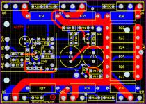
Yes, the single channel J boards will remain unchanged; it will be still possible to use 3 pairs of output devices and if you want to stay close to original design, just leave one pair out.
The only changes/options will be implemented to the daughter board only, like the suggested jfet current source for instance.
The only changes/options will be implemented to the daughter board only, like the suggested jfet current source for instance.
I can either run separate wires from PS to X front end daughter board or take the power directly from output boards, what's the preference?
The positive supply to the LTP sees only the current source and hence is not critical. It may even come from a separate PSU.
The negative rail is critical, as the bottom of the drain resistor has to see exactly the same voltage as the bottom of the source resistor of the bottom (driver) MOSFET. One solution for a 3-board design (which I used successfully before) is to only place the JFETs on the daughter board, and the drain resistors of the LTP on the power boards close to the MOSFETs. That way the connection between LTP and power PCBs is in current mode and the MOSFET gate would be affected much less by connection inductances.
As such, you need to run no negative rail to the daughter board, only +Ve (now possible with separate cap filtering) and (local signal) Ground.
How nice !!
😉
Patrick
Hi Peter!
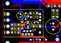
What are you going to use for C1? In your PCB it seems to be an ElCap, while Nelson uses most probably a PP cap according to the pictures of the Firstwatt product published on 6 moons.
(the grey pictured cap seems to be a PP component from BC available at Digikey)
What are you going to use for C1? In your PCB it seems to be an ElCap, while Nelson uses most probably a PP cap according to the pictures of the Firstwatt product published on 6 moons.
(the grey pictured cap seems to be a PP component from BC available at Digikey)
Peter,
The preliminary looks good. One small suggestion before you finalize. Could the mounting holes under the resistors be moved to both ends of the out trace?
Are you working on a PS board as an option?
What size heatsink would be a good match for this Xed J amp. Each channel will be dissapating heat from 8 - 12 devices.
What about heatsink capabilities for the daughter board?
Tad
Some great suggestions, thanks.
Placing R7 off daughter board not only simplifies the layout but also allows for a full size resistor footprint as a bonus.
It looks like the original AJ uses that capacitor: http://search.digikey.com/scripts/DkSearch/dksus.dll?Detail&name=3019PH-ND My personal preference is for quality electrolytic, like BG N but since those are not available any longer in small values, I modified the footprint to accept 1uF BC Components Metallized Polyester cap.
The mounting holes are only there if you need to mount the mosfets off the board, with extension wires. Otherwise the mosfet pins are more than enough to support the board. I can't move them, but with original AJ circuit R22 and R27 are not to be instaled and access to those two mounting holes isn't a problem.
PS boards will be available as well, check this link: http://www.diyaudio.com/forums/showthread.php?postid=1847304#post1847304
Attachments
tryonziess said:
What size heatsink would be a good match for this Xed J amp. Each channel will be dissapating heat from 8 - 12 devices.
What about heatsink capabilities for the daughter board?
I would imagine that at least two of those are needed per channel: http://www.diyaudio.com/forums/showthread.php?s=&threadid=8542&highlight=rtheta
The aren't any requirements for heatsinking the daughter board
Are the power supply / rectifier boards going to be available separately without the amplifier boards?
> Placing R7 off daughter board not only simplifies the layout
Told you, how nice !!
> but also allows for a full size resistor footprint as a bonus.
Hope you are not only laying out for Caddick MK132s, but also Texas naked and Vishay Dales.
😉
> I modified the footprint to accept 1uF BC Components Metallized Polyester cap.
If you need larger values, WIMA has now a MKS2-XL series which goes to 22uF. There are reportedly very very good, sonically.
http://www.wima.de/DE/WIMA_MKS_2-XL.pdf
Of course they also have lower values :
http://www.wima.com/EN/WIMA_MKS_2.pdf
Patrick
- Home
- Amplifiers
- Pass Labs
- Aleph J-X Amp Project

