Thank you for your help. I have been lead to believe that doing things the way they are doing them with the best tube amps is a way of choosing components for state of the art sound from the tranistor. Could you please comment on the choice of the choke I have found tube amp builders are using 7,000 Henrys at 12 Hz, they say it gives a significant increase in quality of the high frequency over all other chokes, is this true ?
you don't have place for that type of choke in Aleph ;
sole place in circuit where you can use choke is in CLC filter in PS , where you need lowest Rdc of them you can manage , because current of entire amp will flow through them . these chokes are either big chunks of enamelled copper wire without core , or same with big iron core ( inductance in range of several mH ) ......... and not small things ordinary used in tube world (inductance in range of several H )
even if you already make purchase of all parts needed for amp ( I resume even without looking at BOM you attached previously) I strongly advise you one thing : hold your horses for few months ; download all pdfs you can find on FIRST WATT HOME and read ........ and read ........ and read ;
more you know , you'll know more how little you know .
having amplifier made isn't most important thing ; what's most important is that you learn how to made it ...... and not just to bring pieces as puzzle , even without knowing what are you exactly doing .
I have no issue with high inductance. but the choke that you have attached cannot handle the current required, and as ZM said, you need low DCR.
The issue I had with your choice is common mode vs standard. The inductors you specified were common mode. Is this how you plan to use your inductors?
if so, it must be able to handle at least double the bias, since the current passes through both the positive and negative sides of the inductor. Add the usual double operating current for a margin and you've got one heck of an inductor. Nothing says this won't work, and may work better than it just makes for huge inductors and there may be an issue with heat.
The inductor you specified http://www.farnell.com/datasheets/78009.pdf probably would work just fine connected as a common mode. You should use one side in the positive rail and another in the negative, a bit different connection than you probably were planning. Connect your transformers as center tapped.
Last edited:
I have no issue with high inductance. but the choke that you have attached cannot handle the current required, and as ZM said, you need low DCR.
The issue I had with your choice is common mode vs standard. The inductors you specified were common mode. Is this how you plan to use your inductors?
if so, it must be able to handle at least double the bias, since the current passes through both the positive and negative sides of the inductor. Add the usual double operating current for a margin and you've got one heck of an inductor. Nothing says this won't work, and may work better than it just makes for huge inductors and there may be an issue with heat.
The inductor you specified http://www.farnell.com/datasheets/78009.pdf probably would work just fine connected as a common mode. You should use one side in the positive rail and another in the negative, a bit different connection than you probably were planning. Connect your transformers as center tapped.
I will use the Farnell #78009 inductor, I know I have to use 4 of them for the two channels, this takes a load off of my mind. Before I buy my parts I need to know how to seporate the circuit board into 3 parts to make the Aleph J-X from it, I am scared that I will not break the boards along the line. Do I have to put the board between two boards and have the cut line on the board facing up while I bend the circuit board down to snap it along the line, or can I just hold it in my hands and bend the board down with the cut line faceing up, or should it be faceing down ? I dont want to buy all of the parts for this board and then make a bad break on them and be unable to replace with the same board due to unavaible supply.
Thank You for your help, I know I have had some bad ideas but did not know why I should not use them untill I have herd back from you.
2 per amp? Are you planning a CLCLC filter? I'm not sure, but I suspect that if you used the common mode chokes as standard chokes, you might saturate the cores. They seem awful small for the inductance and current. Hopefully someone who knows a bit more about common mode inductor implementation will chime in.
Hi SCAIFF001,I will use the Farnell #78009 inductor, I know I have to use 4 of them for the two channels, this takes a load off of my mind. Before I buy my parts I need to know how to seporate the circuit board into 3 parts to make the Aleph J-X from it, I am scared that I will not break the boards along the line. Do I have to put the board between two boards and have the cut line on the board facing up while I bend the circuit board down to snap it along the line, or can I just hold it in my hands and bend the board down with the cut line faceing up, or should it be faceing down ?
F.E.: with OLFA knife point scratch several times over the (deepening) line and PCB will separate. Be attentive in patient...
Hey, don't make your life harder as it is! 😉

Before I buy my parts I need to know how to seporate the circuit board into 3 parts to make the Aleph J-X from it, I am scared that I will not break the boards along the line. Do I have to put the board between two boards and have the cut line on the board facing up while I bend the circuit board down to snap it along the line, or can I just hold it in my hands and bend the board down with the cut line faceing up, or should it be faceing down ? I dont want to buy all of the parts for this board and then make a bad break on them and be unable to replace with the same board due to unavaible supply.
They break naturally along scoring lines like a Kit Kat bar, no additional knife cutting is needed 😉
Attachments
Peter's break version: "Try a little bit harder"They break naturally along scoring lines like a Kit Kat bar, no additional knife cutting is needed 😉

OK, Peter is the boss! 😉
Im after some advise. I want to use 2sj74 as ccs. As far as i can determine I should be using P1 as 100ohms. Do I need a resistor in RP ? too . My psu will be 18v crc. Any advice much appreciated.
oh and another thing would using 4 matched pairs of irfp240 be addequate ? or is 2 quads better ? If So in what configuration should I use the matched fets ? (im sure all 8 matched would be best but I dont have access to that )
Clcrcrc
I believe I have seen Nelson Pass commenting on this but cannot remember where to read it again, I think it was in a Aleph X Amp Builders Fourm comment, as a way it can be done, the CLCRCRC. My memory is not that relable these days due to all of the 220mg Methadone I have been taking every day for years, along with 3.75mg of hypnotic Imovane I take 6 doses a day of it with 100mg of the sedation of diphenolhydromine. I am very stoned all day and love listening to music as I nod out six times a day so I need to have my audio system sound as good as can be because the music system ambiance can mix up with the drug system ambiance and I can drift off as to heaven six times a day. This has screwed up my memory though, I know I have read all(most or some) of the papers I should have but dont retain everything any more, but I do try my best to put in at least 8 hours a day of diyAudio projects either listening to my systems quality and/or reading on how to improve my system, so please be patiant with me I am trying my best all of the time.
I intend to use 99,000microFerrid25VCapacitor + 1.8mH14AmpInductor + 99KuF25VCap + .15ohm50wattResistor + 99KuF25VCap + .25ohm50WResistor + 99KuF25VCap
The 99KuF25VCap=[33,000+33,000+33,000]microFerrid 25Volt Capacitors
There will be additional loss of Voltage so I will use a 20Volt 800VA transformer for each mono channel
Dose this setup look OK ? I believe that I have read about it before but cannot remember where ?
Please help me out with this, I am ready to order parts but keep on putting it off as I have found out that my designs and part choices have not been good ones.
Thank You for your help everybody.
2 per amp? Are you planning a CLCLC filter? I'm not sure, but I suspect that if you used the common mode chokes as standard chokes, you might saturate the cores. They seem awful small for the inductance and current. Hopefully someone who knows a bit more about common mode inductor implementation will chime in.
I believe I have seen Nelson Pass commenting on this but cannot remember where to read it again, I think it was in a Aleph X Amp Builders Fourm comment, as a way it can be done, the CLCRCRC. My memory is not that relable these days due to all of the 220mg Methadone I have been taking every day for years, along with 3.75mg of hypnotic Imovane I take 6 doses a day of it with 100mg of the sedation of diphenolhydromine. I am very stoned all day and love listening to music as I nod out six times a day so I need to have my audio system sound as good as can be because the music system ambiance can mix up with the drug system ambiance and I can drift off as to heaven six times a day. This has screwed up my memory though, I know I have read all(most or some) of the papers I should have but dont retain everything any more, but I do try my best to put in at least 8 hours a day of diyAudio projects either listening to my systems quality and/or reading on how to improve my system, so please be patiant with me I am trying my best all of the time.
I intend to use 99,000microFerrid25VCapacitor + 1.8mH14AmpInductor + 99KuF25VCap + .15ohm50wattResistor + 99KuF25VCap + .25ohm50WResistor + 99KuF25VCap
The 99KuF25VCap=[33,000+33,000+33,000]microFerrid 25Volt Capacitors
There will be additional loss of Voltage so I will use a 20Volt 800VA transformer for each mono channel
Dose this setup look OK ? I believe that I have read about it before but cannot remember where ?
Please help me out with this, I am ready to order parts but keep on putting it off as I have found out that my designs and part choices have not been good ones.
Thank You for your help everybody.
To borrow a page from Andrew T's playbook, take a close look at your capacitor voltage ratings.
First off, @20VAC, you can expect 27VDC (1.4*20-1 for diode losses).
Then add 5% or so for transformer regulation (they are rated at full load so partial load voltage will be higher)
Your mains voltage may be above nominal. Add another 5% or so depending on your grid.
You could see as much as 30V at the input cap. Go for 35V caps.
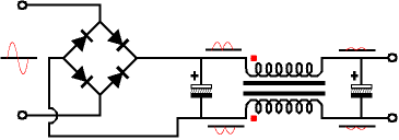
Nothing wrong with the filter topology you have chosen, hopefully someone will say something about the common mode chokes. I think the chokes you have chosen avid core saturation by having the DC component of each rail cancel the magnetizing effect. Compare the core size of your chosen inductor with that of a "500W" inductor like the Erse Super Q.
First off, @20VAC, you can expect 27VDC (1.4*20-1 for diode losses).
Then add 5% or so for transformer regulation (they are rated at full load so partial load voltage will be higher)
Your mains voltage may be above nominal. Add another 5% or so depending on your grid.
You could see as much as 30V at the input cap. Go for 35V caps.
Nothing wrong with the filter topology you have chosen, hopefully someone will say something about the common mode chokes. I think the chokes you have chosen avid core saturation by having the DC component of each rail cancel the magnetizing effect. Compare the core size of your chosen inductor with that of a "500W" inductor like the Erse Super Q.
ERSE Supper Q & Capacitor Choices Vs Long Life & Ripple Quality
http://www.diyaudio.com/forums/newreply.php?do=newreply&p=155523.
Capacitors, there are a few things I am not to shure about. Take an example of Panasonic capacitors, the series T-UP is 3000hours at "85degree Celcius Suitable formost general purpose industrial applications. Extended ratings" stated in Panasonic data sheets, the series TS-HA is 3000hours at "105degree Celcius Long life with high ripple current capability"
stated in the Panasonic data sheet. How are these two electrolytic capacitors performing in the Aleph J-X Poer Supply because the TS-HA series costs about 50% more than the T-UP series of capacitor, here is the address of the Panasonic Capacitor Data Sheet
http://panasonic.com/industrial/includes/pdf/aec_2008.pdf
Also there are Computer Grade Capacitors with a very high price, but I have noticed that many manufactures use these Can Electrolytic
Capacitors for the Power Supply, I have attached the Data Sheet for one Can Computer Grade Electrolytic Capacitor I have been concidering using.
Please give me a little help with this decision noteing that I am trying to build the best amp I can while keeping costs down, I dont want to waist money on Computer Grade Capacitors if it is not nessessary because these are $35-$60 each for high capacitance Cans.
Thank You, your help is much appriciated, I whish I had something I could give back of any value to anyone.
I am going to use the **** Super Q 16gage Inductor, or should there be a 14gage inductor avaible, if the Aleph 3 used ERSE Super Q 2mH 500W 16gage part#266-904 I found this information at the following linkTo borrow a page from Andrew T's playbook, take a close look at your capacitor voltage ratings.
First off, @20VAC, you can expect 27VDC (1.4*20-1 for diode losses).
Then add 5% or so for transformer regulation (they are rated at full load so partial load voltage will be higher)
Your mains voltage may be above nominal. Add another 5% or so depending on your grid.
You could see as much as 30V at the input cap. Go for 35V caps.
Nothing wrong with the filter topology you have chosen, hopefully someone will say something about the common mode chokes. I think the chokes you have chosen avid core saturation by having the DC component of each rail cancel the magnetizing effect. Compare the core size of your chosen inductor with that of a "500W" inductor like the Erse Super Q.
http://www.diyaudio.com/forums/newreply.php?do=newreply&p=155523.
Capacitors, there are a few things I am not to shure about. Take an example of Panasonic capacitors, the series T-UP is 3000hours at "85degree Celcius Suitable formost general purpose industrial applications. Extended ratings" stated in Panasonic data sheets, the series TS-HA is 3000hours at "105degree Celcius Long life with high ripple current capability"
stated in the Panasonic data sheet. How are these two electrolytic capacitors performing in the Aleph J-X Poer Supply because the TS-HA series costs about 50% more than the T-UP series of capacitor, here is the address of the Panasonic Capacitor Data Sheet
http://panasonic.com/industrial/includes/pdf/aec_2008.pdf
Also there are Computer Grade Capacitors with a very high price, but I have noticed that many manufactures use these Can Electrolytic
Capacitors for the Power Supply, I have attached the Data Sheet for one Can Computer Grade Electrolytic Capacitor I have been concidering using.
Please give me a little help with this decision noteing that I am trying to build the best amp I can while keeping costs down, I dont want to waist money on Computer Grade Capacitors if it is not nessessary because these are $35-$60 each for high capacitance Cans.
Thank You, your help is much appriciated, I whish I had something I could give back of any value to anyone.
Attachments
I'm not sure about the current capacity of the Super Q- perhaps the Erse data sheets will help. But, given 500W into 8R is almost 7A I suspect that you will be saturating the cores. You might want to consider air core coils, but see if you can find the data sheets. You can probably use the Farnell common mode chokes with one leg in each rail. referring to the drawing in post 742, the caps will be two caps in series, with the junction being ground. That makes the DC saturating currents cancel.
Caps are a bit of a personal choice, but I think high ripple current capacity and high temperature rating is important. If the heat sinks will be 55C, how hot will it be inside? It may not exceed 85C, but you'll get better life out of 105C caps. I don't think you'll hear much of a difference, but there may be a reliability difference.
There is a free tool called PSUD2. Use it to model the ripple current expected in your caps. It might surprise you, especially if you model your transformer a bit too ideally.
I'm not quite sure what computer grade means, other than the implication of high quality. Look at the data sheets to see if you need the ripple current capacity. Note that you get 50% more ripple capacity with 3 x 33,000uf than a single 100,000 uf. Also the Panasonic caps are rated at higher ripple current than the U36D at the same capacitance/voltage rating. Seems that they are a better value.
Im after some advise. I want to use 2sj74 as ccs. As far as i can determine I should be using P1 as 100ohms. Do I need a resistor in RP ? too . My psu will be 18v crc. Any advice much appreciated.
Please could someone advise me on the Value of RP ?
ok. So I need to measure my 2sj109. I'll have to remove it and test it I guess.... Just gotta find out how to do so.
so i guess in referance to :
" The exact value for the source resistor depends on the Idss. If the Idss is 8mA, the resistor value is 0.
I probably dont need a resistor.....?
" The exact value for the source resistor depends on the Idss. If the Idss is 8mA, the resistor value is 0.
I probably dont need a resistor.....?
- Home
- Amplifiers
- Pass Labs
- Aleph J-X Amp Project