I measured R25 and R26 and R15 and they all look good, I removed the pot and checked it too, all seems fine. is it possible Q4 is just dead ?
It is possible that there is something wrong with it, especially if everything else is good so far.
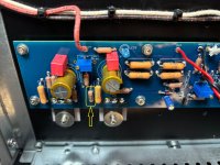
I am curious about R15 in one of the pictures in post #10,235.
R15 is shown as a Dale RN60D with what appeared to be 2207J written on it. I am puzzled by that as from my understanding of the RN60D numbering format, 1k resistance should be specified as 1001 plus the tolerance code.
R15 is shown as a Dale RN60D with what appeared to be 2207J written on it. I am puzzled by that as from my understanding of the RN60D numbering format, 1k resistance should be specified as 1001 plus the tolerance code.
Attachments

Ha... I was just going to write that and post it here....
Here are my boards.... by the way, the 2201J is 2.2Kohms... but these days, everything is possible. That's why I always measure each resistor before it goes in.
You need 2210F....


Here are my boards.... by the way, the 2201J is 2.2Kohms... but these days, everything is possible. That's why I always measure each resistor before it goes in.
You need 2210F....
Last edited:
Check the Q4 orientation... it might be soldered back to front... see the second photo I just added to the previous post.
No I havent touched the offset yet, not sure how that would have any impact on the CCS, so I kind of just put that in the back of my head.
Just wondering whether the other half of the circuit is working.
Getting back to the issue at hand, if the resistors and pot checked out, then it may be that the transistor is faulty and shorting, allowing current to flow through it regardless of the Vbe. You can try measuring the resistance between collector and emitter. In the circuit that would be in parallel with R27 pot, R15, and R16. If the transistor has a short, the resistance would measure low, and adjusting the pot probably would not change the measurement much. However, removing the transistor from the board to check it will give a definitive answer.
Getting back to the issue at hand, if the resistors and pot checked out, then it may be that the transistor is faulty and shorting, allowing current to flow through it regardless of the Vbe. You can try measuring the resistance between collector and emitter. In the circuit that would be in parallel with R27 pot, R15, and R16. If the transistor has a short, the resistance would measure low, and adjusting the pot probably would not change the measurement much. However, removing the transistor from the board to check it will give a definitive answer.
Collecting voltages and seeing some things that make no sense. I fixed my expected voltages on the schematic, forgot the bottom rail wasn't ground, not using to having a dual supply.

take that pic again and delete redundant parts, accordingly to your assembly
post here
I'm asking you to delete parts you didn't populate from schematic, so we (I) can be sure what's actual situation

Ok I am just lost and frustrated. I checked the voltage across r8 of 8.4v, so about 8.4mA is flowing through that current source. Both gates of Q1a/b are at ground so I assume the current is dividing equally. The voltage across r7 is 4.8v, and adjusting r7 has no impact on the voltage. How is it possible that the voltage doesn’t change when I adjust the resistance of the pot ?
R7 sets the DC offset.... I thought you couldn't change the bias (locked at 550mV across each of the R16/17/18/19)..??
Do you also have a problem with DC offset (unable to trim it)??
If DC parameters look okay, apply a very low pp 1kHz sinewave at the front and look for the amplified, undistorted (unclipped) sinewave signal at the output - no load. That will further help with fault finding.
Here's the sheet I prepared earlier... I already removed the confusing resistors and links... you may find it useful.

with the amp plugged directly into the wall the voltage across r18 increases to 550mv
Do you also have a problem with DC offset (unable to trim it)??
If DC parameters look okay, apply a very low pp 1kHz sinewave at the front and look for the amplified, undistorted (unclipped) sinewave signal at the output - no load. That will further help with fault finding.
Here's the sheet I prepared earlier... I already removed the confusing resistors and links... you may find it useful.
Basically both pots don’t seem to do anything. All 4 mosfets are drawing about 1.25A which I am concerned will burn out my transformer. The transformer already has a buzz to it when I turn the power supply on. I measured all the voltages in the amp and nothing stands out as wrong. It’s just the bias current is too high and I cannot reduce it. The offset is about 100mv on the output and I cannot adjust that either. I have no idea where else to look other than one of the active devices might be burned out ?
- Home
- Amplifiers
- Pass Labs
- Aleph J illustrated build guide