I too run Aleph J with sensitive horns and can only hear any noise in a silent room with my head near the horn. What type of noise Is it? There is very little hiss but I’ve found Aleph J quite fussy about internal layout when it comes to buzzes and hums! As suggested, internal pics may help.I am running Aleph J amps with 110db sensitive horns. When the amp is connected to just the speaker (XLR unplugged) there is an audible level of noise which is off-putting at low levels of listening. The noise doesn't change when the input is connected.
Should the Aleph J be silent? Boards were purchased from Diyaudio store, perhaps the noise is from the power supply configuration not the pcb's.
I can post an internal picture of this will assist?
Balanced interconnects will increase CMRR by 60db in this circuit if I remember correctly. So this is something I am considering for the long term.
that said, very quiet with 92db sens speakers. With shorted inputs it is just possible to identify the amp is on by putting the ear physically against the cone. No hum, PSU way too overspecced for that. But more like hearing the sea from a distance. Right now uncertain whether it is due to the amp or speaker wires picking stuff up. Found it difficult to scope noise at the outs (I prolly goofed, as no difference in noise when turning off amp) but plan on redoing it 🙂
For higher sens I think I would have to redo a bit here and there wrt twisting and routing. SE unfortunately tends to be more delicate than PP amps wrt noise pickup iow less noise rejectant.
I deliberately tried to set up the amp without twisting speaker output wires and DC wires from PSU to boards, as a test. Given some time and motivation, a bit more twisting will be done. Allready shortened the signal wires and retwisted, made it perhaps a little bit more quiet.
but no need in changing a winning team, unless I go for far more sensitive speakers. But the J is rather gainy, so I don’t think I will in the current setup with a 2V3 source SE that will be 4V5 if I go balanced.
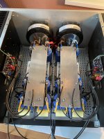
attached is a photo of the nearly completed amp. Posted before, but anywz.
regards,
Andy
that said, very quiet with 92db sens speakers. With shorted inputs it is just possible to identify the amp is on by putting the ear physically against the cone. No hum, PSU way too overspecced for that. But more like hearing the sea from a distance. Right now uncertain whether it is due to the amp or speaker wires picking stuff up. Found it difficult to scope noise at the outs (I prolly goofed, as no difference in noise when turning off amp) but plan on redoing it 🙂
For higher sens I think I would have to redo a bit here and there wrt twisting and routing. SE unfortunately tends to be more delicate than PP amps wrt noise pickup iow less noise rejectant.
I deliberately tried to set up the amp without twisting speaker output wires and DC wires from PSU to boards, as a test. Given some time and motivation, a bit more twisting will be done. Allready shortened the signal wires and retwisted, made it perhaps a little bit more quiet.
but no need in changing a winning team, unless I go for far more sensitive speakers. But the J is rather gainy, so I don’t think I will in the current setup with a 2V3 source SE that will be 4V5 if I go balanced.
attached is a photo of the nearly completed amp. Posted before, but anywz.
regards,
Andy
Attachments


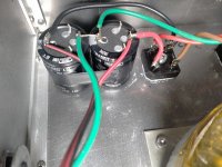
not sufficient filtering, bad wiring, especially of GND
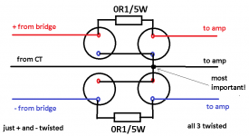
will sketch in evening, if no one chime in, in meantime
will sketch in evening, if no one chime in, in meantime
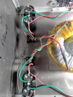
here it is
"most important" means - absolutely equidistant to upper and lower cap
easier to obtain when having pcb or using screw contacts caps, so one can use AL plate for proper GND organisation, moving GND takeout point from charging current paths
in this case (PtP), best possible solution
"most important" means - absolutely equidistant to upper and lower cap
easier to obtain when having pcb or using screw contacts caps, so one can use AL plate for proper GND organisation, moving GND takeout point from charging current paths
in this case (PtP), best possible solution
Attachments
considering efficiency of his speakers, what I drew is minimum
I see. I just love this new Facebook functionality 
Haven’t modeled it in PSUD, but he is prolly going to need reduced Iq to tackle the ripple.
Haven’t modeled it in PSUD, but he is prolly going to need reduced Iq to tackle the ripple.
Thank you all kindly for the advice, I will follow your well considered advice and report back. Cheers
Attachments
Universal PSU boards came today so on with Aleph J build. In measuring the resistors before dropping them into the boards I found that all of the R1-R8 resistors which are supposed to be .47 ohms 5% came out consistently in the .6 and .7 range-- more than 5%. None were .5 Is this OK? Multi meter error?
Good advice! When shorted I get .1 to .2 ohms. The reading on each resister oscillates between .5 and .6 after I keep the probes on for 30 seconds or so. It doesn't stabilize to one value. I'm thinking that subtracting the .1-.2 from these values gets me in range unless that's just wishful thinking on my part.
You'll be fine by subtracting that shorted value.
Your lead's resistance is now significant compared to the values you are trying to measure and has to be accounted for. There are techniques for accurately measuring low resistance values (for example, 4 wire measurement or voltage drop across the resistor when fed a known stable current). But for this usage just subtracting is quite adequate.
Your lead's resistance is now significant compared to the values you are trying to measure and has to be accounted for. There are techniques for accurately measuring low resistance values (for example, 4 wire measurement or voltage drop across the resistor when fed a known stable current). But for this usage just subtracting is quite adequate.
Universal PSU boards came today so on with Aleph J build. In measuring the resistors before dropping them into the boards I found that all of the R1-R8 resistors which are supposed to be .47 ohms 5% came out consistently in the .6 and .7 range-- more than 5%. None were .5 Is this OK? Multi meter error?
What would you want to measure these resistors anyway?Good advice! When shorted I get .1 to .2 ohms. The reading on each resister oscillates between .5 and .6 after I keep the probes on for 30 seconds or so. It doesn't stabilize to one value. I'm thinking that subtracting the .1-.2 from these values gets me in range unless that's just wishful thinking on my part.
in parallell in a PSU with these values, exact value is quite irrelevant as long as the actually conduct. Measuring them exact is far more trouble than what you might get out of it. IMO.
Last edited:
I kinda guessed that was the case. The most important thing is to get the right resistor (value) in the right spot. Matching them is of course nice, but not essential. For PSU filter resistors and output stage source resistors, 5% is good enough as far as matching is concerned 🙂I'm a nooby and you guys have put the fear of NOT measuring resisters in me!! But thanks for the replies. The psu boards are populated and I'm moving on to putting them in the chassis, connecting and testing.
But better safe than sorry, so kudos to you for that!
good luck!! 🙂
Regards,
Andy
Everything is set up and ready for testing. Just finished the dim bulb tester. Can it work on humans?
- Home
- Amplifiers
- Pass Labs
- Aleph J illustrated build guide