Nothing to worry about, perfectly normal.Setting bias and offset correctly?
I've been seeing some bias and offset drift, but not sure if it's normal. I've been trying to run the amp with the bias at 0.430V. I can get that dialed in, w/ offset at 0, then come back in a few hours and the bias has dropped. It usually drops to 0.425V and the offset goes to 0.001 to 0.002mV. Should I be concerned about his amount of drift?
When setting the bias and offset, should the amp have inputs plugged in and speakers connected?
you should always readjust the Iq/bias and offset after letting the amp reach termal equilibrium. Meaning after an hour or so after turning it on.
short the inputs for this process, and disconnect speakers. Though, wrt shorting, I haven’t seen much difference really.
that said, your values even after drift are absolutely nothing to worry about. The Aleph 3 had 50mV or so of offset. Iow you are perfectly safe 🙂
extra good stability, just chill
shorted inputs, no load
everything setting in thermal equilibrium - when amp is hot
shorted inputs, no load
everything setting in thermal equilibrium - when amp is hot

Input shorted, nothing connected to the amplifier output
As the amplifier gets hotter, its quiescent current will drop a bit.... nothing to worry about. Your actual values look really good.
Those offset readings are simply fantastic. (maybe 0.0001 to 0.002V, i.e. 1 - 2 mV ??). Again, nothing to worry about.
I have + and - 10mV (20mV drift) and it is completely fine (I have C1 bypassed).
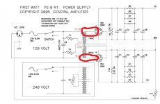
I have a question regarding the wiring of the secondary windings of the transformer to the monolithic bridges. From the schematic of the F6 power supply (I assume that the same wiring works for the Aleph J) (by the way, I am using the universal power supply pcb along with monolithic bridges), it looks as if the upper (or dot) end of the top winding is attached to the terminal to the left of the DC + terminal on one bridge and that the lower (or non-dot) end of the bottom winding is attached to the terminal to the left of the DC + terminal. However, in all the photos of builds by diyaudio members I can find, it looks as if the dot end of each winding is attached to the left of the DC + terminal (see sample photo of one such build). Does it make any difference, which end of the coil is attached to the left of the + terminal? Thanks for any help anyone can give me,
Jazzzman
Jazzzman
Attachments

Hello,
I bought a cheap oscilloscope to play with, and made this dummy load out of a 100 watt 8 ohm resistor attached to a heat sync and attached to a banana to BNC adapter so I can look at the output of my amps. I am using a BNC cable to to go into the oscilloscope in place of a probe, so this thing becomes the probe.
I've used it on my F6 to measure where clipping begins and looked at the harmonic distortion levels with the scope's FFT and it all works fine. However, I read somewhere a long time ago that special care must be taken when hooking up an oscilloscope to a differential amplifier because of something to do with grounding. I think the Aleph J is a differential amp. I am using the Aleph J with single ended input only.
Is this thing safe to hook up to the outputs of the Aleph J?
Is it safe to hook it up to the outputs of a differential bridged amplifier?
I don't want to destroy anything.
Thanks,
Alan
Hello,
I bought a cheap oscilloscope to play with, and made this dummy load out of a 100 watt 8 ohm resistor attached to a heat sync and attached to a banana to BNC adapter so I can look at the output of my amps. I am using a BNC cable to to go into the oscilloscope in place of a probe, so this thing becomes the probe.
I've used it on my F6 to measure where clipping begins and looked at the harmonic distortion levels with the scope's FFT and it all works fine. However, I read somewhere a long time ago that special care must be taken when hooking up an oscilloscope to a differential amplifier because of something to do with grounding. I think the Aleph J is a differential amp. I am using the Aleph J with single ended input only.
Is this thing safe to hook up to the outputs of the Aleph J?
Is it safe to hook it up to the outputs of a differential bridged amplifier?
I don't want to destroy anything.
Thanks,
Alan
View attachment 1068623
The dummy load is okay to use with Aleph J. If you have 2 dummy loads, you could load both channels at the same time AND you could monitor both channels with the oscilloscope. No need to worry about 2 probes having the same common.
The dummy loads are okay to use with a bridged amplifier as well; HOWEVER, you will need differential probes to monitor both channels at the same time on the oscilloscope. Otherwise, the probes' common returns would short the bridged amplifier outputs... because with a bridged amplifier, the negative speaker terminals are NOT sitting at the same potential.
Member 6L6 just successfully cobbled together a test jig which let him display a bridged amplifier's output on an oscilloscope. The arrangement included a 2 channel oscilloscope and two standard (10X, 100 MHz) scope probes.
Amp was a bridged F6 if I recall correctly.
Amp was a bridged F6 if I recall correctly.
Hey Everyone - Im using the Blogspot build guide. R1 for the amp boards shows up twice in the saved Mouser cart. The values are different.
https://www.mouser.com/ProjectManager/ProjectDetail.aspx?AccessID=35ACFA214D
Is that just an error? Which of the two should I use?
https://www.mouser.com/ProjectManager/ProjectDetail.aspx?AccessID=35ACFA214D
Is that just an error? Which of the two should I use?
You can check against the BOM. The R1 for the PSU is different - it’s the 3W. Also the customer field for the 221R resistors get’s cut off. It’s 12, but looks like 1 on the website.Hey Everyone - Im using the Blogspot build guide. R1 for the amp boards shows up twice in the saved Mouser cart. The values are different.
https://www.mouser.com/ProjectManager/ProjectDetail.aspx?AccessID=35ACFA214D
Is that just an error? Which of the two should I use?
I'm to the point where I'm stuffing capacitors but have an issue with spacing for C3 and C6. The 1uf WIMA caps don't fit with the ELNA Silmic II 50V which has 7.5mm lead spacing and uses the larger footprint. Does anyone have a suggestion for a MKP type cap for the C6 position that would fit (between C3 and R29).
Successfully powered up and biased two channels (one at a time of course) using a lab power supply. This build started six months ago and has been worked on intermittently. Apparently I never set the pot at R27 to 68K, so bringing the voltage up to just 5V increased voltage across R18 to .5V. After some fiddling with increasing resistance on R27 and then slowly increasing voltage, I finally got to .4V on R18 at 24V.
I had some fun playing around with voltage and bias to see how it effected output and distortion. Turning the supply voltage up to 30V and biasing at .45V seemed to give good results. Not sure if it's a good idea to run it this way when installed in it's chassis...but I'm willing to try it. The heat sinks run at about 50C, but the source resistors run 56C. Is this a problem for those resistors?
I had some fun playing around with voltage and bias to see how it effected output and distortion. Turning the supply voltage up to 30V and biasing at .45V seemed to give good results. Not sure if it's a good idea to run it this way when installed in it's chassis...but I'm willing to try it. The heat sinks run at about 50C, but the source resistors run 56C. Is this a problem for those resistors?
resistors, nope
check datasheets, you'll be surprised what's normal for them
though , take care of mosfet dissipation and also what is actual voltage across JFets
that, if you intend to increase rails
check datasheets, you'll be surprised what's normal for them
though , take care of mosfet dissipation and also what is actual voltage across JFets
that, if you intend to increase rails
Where do I take this measurement and what does across JFet mean?what is actual voltage across JFets
I believe Zen Mod wanted you to check the power dissipated by the Jfets and Mosfets to make sure you are not exceeding their maximum safe operating values and risk destroying them.
So you need to know the voltage drop across/through them and the current through them to calculate the power dissipated. The voltage drop is measured from drain to source, so measure VDC with probes at drain and source. To determine the current measure the voltage drop across the Mosfet source resistor and use Ohm's Law to calculate the current. To determine the current through the Jfets, a similar measurement is also needed. There are resistor(s) in the Jfet circuit that can be used. A resistor or pot that is in series with the Jfets may be measured for voltage drop and knowing the resistance, the current can be calculated. Post your Aleph J schematic if in doubt.
I think Zen Mod is also concerned that the Jfets' maximum voltage is not exceeded. Jfets in general have a low maximum voltage Vds.
As Zen Mod mentioned, data sheets may be checked for maximum dissipation of the Mosfet/Jfet. The maximum dissipation is usually given at 25 degrees C, and derating is needed for actual operating temperature. If no derating chart is given, typically a factor of 4 or so is used.
Hi all. I've not posted in a while cos I've been loving my F4 for a couple of years.
Now I'm stuffing the Aleph J boards:0).
How about a paper in oil cap at C1?
Now I'm stuffing the Aleph J boards:0).
How about a paper in oil cap at C1?
How about building it stock, and then make changes down the road?How about a paper in oil cap at C1?
- Home
- Amplifiers
- Pass Labs
- Aleph J illustrated build guide