Where u live?I tested the psu this morning. Everything fine. 26.8 volts all around. Thanks to everybody for helping me get this far. Maybe the AJ boards will be stocked this week??
Well, i have got to tell ya - the Aleph Jeys are two very hot and cool not at all polite but lovely smooth kittens in my setup.
Never ever the electric harchness.
The combination of the extreme knife sharpe intelligibility, a lean and strongly present sound image clarity and total sense of control: In combination with a rich, chocolate midrange and treble, and a lush, rich, and very strong bass. With a healthy touch of musical life like and very happy bounce.
This is the true end game amplifiers for me😎💕
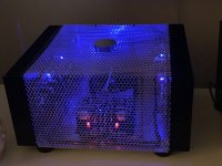
Attached picture. Test fitting the hexagonal aluminium mesh covers for the very hot cool kittens🤗
If you dont like them open air hex meshed Alephs? Just, crankit up and Enjoy the very old skool kool music video:
Sorry😇 i forgot. Edit: Got bass?? 😊
Never ever the electric harchness.
The combination of the extreme knife sharpe intelligibility, a lean and strongly present sound image clarity and total sense of control: In combination with a rich, chocolate midrange and treble, and a lush, rich, and very strong bass. With a healthy touch of musical life like and very happy bounce.
This is the true end game amplifiers for me😎💕
Attached picture. Test fitting the hexagonal aluminium mesh covers for the very hot cool kittens🤗
If you dont like them open air hex meshed Alephs? Just, crankit up and Enjoy the very old skool kool music video:
Sorry😇 i forgot. Edit: Got bass?? 😊
Attachments
Last edited:
I got a request. ”What about a little touch of the lovely sub bass.”
Ok. 😊
https://tidal.com/track/170594746
Edit:
Enjoy 😎
Ok. 😊
https://tidal.com/track/170594746
Edit:
Enjoy 😎
hope you have C bank in amp case, too
and - using mains dedicated hardware for DC routing (IEC?) ...... well, it calls for trouble, even in case of having warning message near them
someone, sometime ....... will ignore warning and push mains cable there .......
and - using mains dedicated hardware for DC routing (IEC?) ...... well, it calls for trouble, even in case of having warning message near them
someone, sometime ....... will ignore warning and push mains cable there .......
No bank in amp case at this point. Would be easy enough to add.hope you have C bank in amp case, too
and - using mains dedicated hardware for DC routing (IEC?) ...... well, it calls for trouble, even in case of having warning message near them
someone, sometime ....... will ignore warning and push mains cable there .......
I did consider not using mains hardware, but as I am the only one using it....
first wrong
second, also wrong
but, don't let me be rain on your parade ...... even if I did made both of these and just later recognized them as mistakes
second, also wrong
but, don't let me be rain on your parade ...... even if I did made both of these and just later recognized them as mistakes
Placing a power supply in a separate box requires a fair bit of understanding related to what should an ideal power supply provide to a circuit, and at what frequencies.
That large capacitors' bank, together with a combination of smaller capacitors mounted as close as possible to amp PCB, while taking care of DC wiring length and thickness, would've provided much better results.
What you really want is as low the impedance as possible for all audio frequencies, between PS PCB and AMP PCB MOSFETs. So, for low frequencies you need a large capacitors bank mounted as close as possible to MOSFET's, for mid/high frequencies (AND depending on the length and thickness of the DC wiring), you'll need a combination of something like 10-22uF, a 1uF and a 0.1uF capacitors.
Some people use around 50uF motor start film capacitors, which will also work nicely...
It is ll part of the learning curve... in the end, and improving the performance.

Hi, I don't know if that's the right place for this question, I just bought the power pcb for Aleph J from diyaudio store. I found a parts list (bom) but it doesn't open, I'd like to know if there is a parts list somewhere or if you can advise me which capacitors or resistors are best suited to power Aleph J.
Thanks
Gianni
Thanks
Gianni
https://www.diyaudio.com/community/...cuit-board-v3-illustrated-build-guide.244788/
I can't get the BOM linked here to work either. Perhaps one of the moderators could address this?
I can't get the BOM linked here to work either. Perhaps one of the moderators could address this?
No stress.Thank you andynor!
wrt parts, for J and most FW’s, I would choose 18k-22k caps with low ESR, snap in type. 2K2 3W bleeders, LED dropping resistors of your own choosing, 4x0R47 3 watt filter resistors per rail. That should cover the basics, sans euroblocks and blade terminals. I you have built before, I would recommend soldering directly to the pcb. The euroblocks are flexible, but can barely take a tightening without deforming. Needless to say I prefer things really tight 🙂
Last edited:
1) I found these capacitors on Mouser: 22000uf 35v esr 24 mOhms. Cornell Dubilier, Mfr. No: SLP223M035H9P3. price: 7.25 euros each. I ask if they are good enough. Audio capacitors is impossible because I would have to buy at least 200 pieces. There are other capacitors with better esr but they cost a lot more.
2) What value should I use for input snubber resistor and for input snubber capacitor?
Sorry for my English, I use google translate.
2) What value should I use for input snubber resistor and for input snubber capacitor?
Sorry for my English, I use google translate.
Input snubbers: I recommend you drop/omit those if you don’t have a Quadimodo test jig, or can find your specific transformer allready tested in the thread naned approximatelt Quasimodo - test results only.1) I found these capacitors on Mouser: 22000uf 35v esr 24 mOhms. Cornell Dubilier, Mfr. No: SLP223M035H9P3. price: 7.25 euros each. I ask if they are good enough. Audio capacitors is impossible because I would have to buy at least 200 pieces. There are other capacitors with better esr but they cost a lot more.
2) What value should I use for input snubber resistor and for input snubber capacitor?
Sorry for my English, I use google translate.
don’t worry, be happy

Link to test results. One can even choose to buy a tranny allready tested.
https://www.diyaudio.com/community/threads/quasimodo-results-only.313202/
https://www.diyaudio.com/community/threads/quasimodo-results-only.313202/
Setting bias and offset correctly?
I've been seeing some bias and offset drift, but not sure if it's normal. I've been trying to run the amp with the bias at 0.430V. I can get that dialed in, w/ offset at 0, then come back in a few hours and the bias has dropped. It usually drops to 0.425V and the offset goes to 0.001 to 0.002mV. Should I be concerned about his amount of drift?
When setting the bias and offset, should the amp have inputs plugged in and speakers connected?
- Home
- Amplifiers
- Pass Labs
- Aleph J illustrated build guide