Question for the experts.
Looks like the store hopes to have the current Aleph J boards back in stock in 1-2 months. They currently have the matched transistor sets in stock. I need to place a order for some the precious Jfets for my mini ACA, was going to go ahead and grab the Aleph J transistor set because knowing my luck by the time the amplifier boards are in the transistors will be out of stock.
So the million dollar question. I have made through all 8.3K posts in this thread and looks like since this summer there have been some prototype Aleph J boards being beta tested. Best I can tell they aim to simplify the Aleph J build process by:
Eliminating all the resistor/pot/jumper options initially built in to navigate potential Jfet shortages making it easier for us noobs to navigate
Ease access parts by moving to IRFP140, 1 up and 1down, which eliminates the need for output Mosfet matching
By reducing output Mosfets should allow easier diagnosis of malfunctioning boards (less fets and source resisters to test)
And probably some other fine details I'm missing as a noob.
Is there any expected sonic improvements with these changes? If not and someone feels comfortable building the current boards is there any downside to grabbing the current version? I really was really looking forward to filling up all the free space for C1 on the current boards with some >$100 film caps filled with Zen Mod's tears.
The prototype builds I’ve seen so far used IRFP150 parts, sort of equivalent to a pair of IRFP240 at each location. One can imagine other device selections. Just another set of options for FAB once they become available on the store.
One thing to keep in mind is that with a single device per rail the dissipation on the device is significantly higher and you need to ensure it is very well mounted to the heatsink using the best interface material.
I believe the new version includes the Newby mod to the Aleph current source, a modified current source to the front end and cascoding of the jfets.
I believe the new version includes the Newby mod to the Aleph current source, a modified current source to the front end and cascoding of the jfets.
Yes, one device per rail is pretty scary. I even had to use tape to ensure mine were safely fastened @ 0N1 
greenhorns are never scared. If we get scared, it is because of explosions ensuring the mileage nescessary to rise from the GH status. I try to speed up the process, hence tape.
we love heat.
But yes, heat transfer is important. Keratherm red and torque wrench are musts.
mine dissipate 42 watts per device. Goal was 50 but the pots ran out of range. So for now I have settled with 42
Regards,
Andy
Last edited:
My acoustic dreams have been crushed! A fine gentleman from www.eBay.sr guaranteed he sold the finest film capacitors to allow reaching audio nirvana, the secret ingredient being ZMs finest tears. A new GH fool is born every day.
Back to our regularly scheduled program, build the current store board if your OK with buying matched transistors from the store and can follow directions carefully?
Back to our regularly scheduled program, build the current store board if your OK with buying matched transistors from the store and can follow directions carefully?
Last edited:
nothing to be scared of up to 35W per mosfet
mica & goop being perfect
up from there ( to say 50W as magical figure with perfect thermal arrangement) - Keratherm, using torque thingie ( overtightening is trouble, area around screw hole sinking in Keratherm more than pins side)
or Alumina pads & goop, not so critical for torque, so common sense being precise enough
all in all , majority of Greedy Boyz are Weaklings, choosing Weakling cases ( 4U/300, just because of few holes and taps being pre-done), so presumed dissipation per mosfet is equally Weakling area - 35 to 40W per device being I'm done and gone for good!!!! borderline
I’m @42 now, but as you know I am never done for goodnothing to be scared of up to 35W per mosfet
mica & goop being perfect
up from there ( to say 50W as magical figure with perfect thermal arrangement) - Keratherm, using torque thingie ( overtightening is trouble, area around screw hole sinking in Keratherm more than pins side)
or Alumina pads & goop, not so critical for torque, so common sense being precise enough
all in all , majority of Greedy Boyz are Weaklings, choosing Weakling cases ( 4U/300, just because of few holes and taps being pre-done), so presumed dissipation per mosfet is equally Weakling area - 35 to 40W per device being I'm done and gone for good!!!! borderline
priorities, priorities. Assembling B1K now. Finished everything but the JFETs yesterday. Then changing drivers in the Super Pensils, old ones are shot. Then perfect the amp 🙂 Like I told you I wanna go to 52 watts per device, 2A2. But that being stated as foolish, maybe 50 is good enough. From time to time I use the amp as a hand heater. Need some dissipation then.
You might be interested in Generg simulations from post #5,744Like I told you I wanna go to 52 watts per device, 2A2.
At some bias point simulation show phase change from negative H2 to positive H2.
I never found it was tested in real Aleph J.
Will check out. Tbh, I don’t feel this proto amp has much distortion as isYou might be interested in Generg simulations from post #5,744
At some bias point simulation show phase change from negative H2 to positive H2.
I never found it was tested in real Aleph J.
so main intention if I increase is to increase class A pocket. If at all needed…
Shielding, what works??
I am considering building cages for the complete PSU units and IEC inlet with the goal to shield them from the audio boards:
Or. Would this be completely useless?
Perforated Sheet Aluminium RV3-5 Aluminium 1.5 mm
https://www.amazon.se/dp/B077M56VFP/ref=cm_sw_r_cp_api_glt_i_883KKW41NHZB8VQ54PS3?psc=1
Nothing is completely useless. People have reported measurably reduced noise levels and improved sound doing similar things. And the best and most expensive Pass amps have external supplies.Shielding, what works??
I am considering building cages for the complete PSU units and IEC inlet with the goal to shield them from the audio boards:
Or. Would this be completely useless?
Perforated Sheet Aluminium RV3-5 Aluminium 1.5 mm
https://www.amazon.se/dp/B077M56VFP/ref=cm_sw_r_cp_api_glt_i_883KKW41NHZB8VQ54PS3?psc=1
that said, you have two dead silent (and snubbered?) Toroidy audio grade trannies. So diminishing returns may kick in very early, so you need to consider whether it is worth the hassle.
in your shoes, I think I would have tried without, and if nevrosa creates sleepless nights, just add later.
I considered doing the same, but my poor metal working skills made me drop it. That and little spare time on my hands.
regards,
Andy
I have AJ boards.My acoustic dreams have been crushed! A fine gentleman from www.eBay.sr guaranteed he sold the finest film capacitors to allow reaching audio nirvana, the secret ingredient being ZMs finest tears. A new GH fool is born every day.
Back to our regularly scheduled program, build the current store board if your OK with buying matched transistors from the store and can follow directions carefully?
regards,
Andy
Nothing is completely useless. People have reported measurably reduced noise levels and improved sound doing similar things. And the best and most expensive Pass amps have external supplies.
that said, you have two dead silent (and snubbered?) Toroidy audio grade trannies. So diminishing returns may kick in very early, so you need to consider whether it is worth the hassle.
in your shoes, I think I would have tried without, and if nevrosa creates sleepless nights, just add later.
I considered doing the same, but my poor metal working skills made me drop it. That and little spare time on my hands.
regards,
Andy
Yea, that sounds very reasonable, but i think it is fun to have good possible tweaks witch could be added to the amplifiers down the road. I really enjoy the building process, and figuring out things. So i am at the same time extremely curious to get them amps warmed up and singing, but i dont want the Aleph J project to come to an end.
Well you know, thats more than slightly crazy thinking. But i am having fun, so no real harm done
 👍
👍Thinking out loud: Wonder if it is any major sonic diffrence and difference i shilding capacity between solid aluminium sheet and fine mesh aluminium sheet shielding?🤔🙂
Out of my league, but meshed would perhaps create more of a Faraday cage kind of effect. I have seen people in the forum using / testing mesh with good results, but don’t remember which thread it was.Yea, that sounds very reasonable, but i think it is fun to have good possible tweaks witch could be added to the amplifiers down the road. I really enjoy the building process, and figuring out things. So i am at the same time extremely curious to get them amps warmed up and singing, but i dont want the Aleph J project to come to an end.
Well you know, thats more than slightly crazy thinking. But i am having fun, so no real harm done
Thinking out loud: Wonder if it is any major sonic diffrence and difference i shilding capacity between solid aluminium sheet and fine mesh aluminium sheet shielding?🤔🙂
It is fun building for perfection. I spent so much time on my PSU, that I had to settle when that and the amp boards turned out nice. I guess there is always room for improvement 🙂
Another thing to consider: would steel mesh be more effective than aluminum?
Possibly less of a consideration for amps that don’t use signal transformers for part of their input gain stage, but worth trying.
Possibly less of a consideration for amps that don’t use signal transformers for part of their input gain stage, but worth trying.
Yes, or possibly copper mesh? It is very easy to bend, form and solder 🙂Another thing to consider: would steel mesh be more effective than aluminum?
Possibly less of a consideration for amps that don’t use signal transformers for part of their input gain stage, but worth trying.
https://www.copper-mesh.com/coppermesh/copper-shielding-mesh.html
So, after completing and setting up my two Aleph J boards I threw some stuff from my signal generator at the boards, with an (to my eyes) odd result: looking at a 10kHz square wave, 0.5V input (neg imput to gnd), no load at the output, I see the expected round off of the raising edge of the wave, but also two small humps(?) on the falling edge. Same on both boards, which otherwise behave nicely at 0.85A bias.
Any idea what causes those ditches on the falling edge at the output? (yellow is input, purple is output)
Any idea what causes those ditches on the falling edge at the output? (yellow is input, purple is output)
Attachments
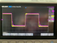
Have you tried with an 8 Ohm dummy load @ the outputs? Perhaps it will look different?So, after completing and setting up my two Aleph J boards I threw some stuff from my signal generator at the boards, with an (to my eyes) odd result: looking at a 10kHz square wave, 0.5V input (neg imput to gnd), no load at the output, I see the expected round off of the raising edge of the wave, but also two small humps(?) on the falling edge. Same on both boards, which otherwise behave nicely at 0.85A bias.
Any idea what causes those ditches on the falling edge at the output? (yellow is input, purple is output)
regards,
Andy
- Home
- Amplifiers
- Pass Labs
- Aleph J illustrated build guide