The bad channel has faulty JFETs, most likely.
There's no current running through JFETs. This current is required to run through them to generate the 4.3V across R7 (1k) - which opens the MOSFETs (puts them in a conductive state). So, your MOSFETs are not conducting the current (each "branch" should be conducting around 1.5 - 2 amps)... -> hence, the speaker terminal (positive) is floating at the V+ potential.
Is Q2 the correct part (NOT the ZTX450)? Inserted the right way around into the PCB?
Is the trim-pot properly soldered AND of the proper value?
Did you use a wrist-strap connected to the ground, when you handled the JFETs?
From your post, it seems like you have already checked the above...., so I'd say it's the JFET's.... try with a new pair.
Good luck.
Reading across the R7 in bad channel - is about 1K ohms, (reading of pot off the board was .996K ohms. In the Good channel, it reads about 100R.
I am struggling to digest what you wrote above.... It almost seems like that the trim-pot in the bad channel is an "open circuit", i.e. its wiper may have burnt out or something.... silly....
Can you take that trim-pot off the PCB, and then either measure it (do you know how to check the trim-pot?) or just replace it with a brand new one?
Make sure that the trim-pot is properly soldered to the PCB....
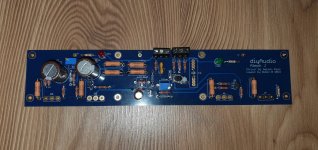
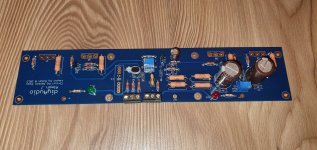
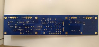
If you have the boards already removed... post the well-lit high res, in-focus photos, please.
The bad channel has faulty JFETs, most likely.
There's no current running through JFETs. This current is required to run through them to generate the 4.3V across R7 (1k) - which opens the MOSFETs (puts them in a conductive state). So, your MOSFETs are not conducting the current (each "branch" should be conducting around 1.5 - 2 amps)... -> hence, the speaker terminal (positive) is floating at the V+ potential.
Is Q2 the correct part (NOT the ZTX450)? Inserted the right way around into the PCB?
Is the trim-pot properly soldered AND of the proper value?
Did you use a wrist-strap connected to the ground, when you handled the JFETs?
From your post, it seems like you have already checked the above...., so I'd say it's the JFET's.... try with a new pair.
Good luck.
Thanks, I haven't though checked the voltage across R7, so this may be be a good one to check and if not correct, then this probably confirms a JFET problem. I had checked the others, but will double check again later today.
The only thing I didn't do was use a wrist strap, but, I did continually ground myself. For one of the boards, I did solder in one of the JFETS the wrong way round, so had to unsolder it and maybe the heat damaged it.
Regarding Aleph Js (or any others) with dual mono PSUs, is it preferred to keep DC grounds separated from one another (or at least isolated with their respective CL60s to earth)?
I would recommend this, yes. I did this with my KSA50 clone, and don't have any issues. Basically 2 monoblocks, but in the same case. Even have a dual power switch so that each transformer has it's own switch and mains fuse.
Last edited:
Davidjt....good point....wise!
Wise after the event, as per usual.
The monoblock cases I found on ebay ('2515 Aluminium Single radiator Enclosure....') took just ten days to arrive from China. While not quite as up-market as the Italian offerings, they are good value imo.
The bad channel has faulty JFETs, most likely.
There's no current running through JFETs. This current is required to run through them to generate the 4.3V across R7 (1k) - which opens the MOSFETs (puts them in a conductive state). So, your MOSFETs are not conducting the current (each "branch" should be conducting around 1.5 - 2 amps)... -> hence, the speaker terminal (positive) is floating at the V+ potential.
Is Q2 the correct part (NOT the ZTX450)? Inserted the right way around into the PCB?
Is the trim-pot properly soldered AND of the proper value?
Did you use a wrist-strap connected to the ground, when you handled the JFETs?
From your post, it seems like you have already checked the above...., so I'd say it's the JFET's.... try with a new pair.
Good luck.
Thanks for your help Extreme_Boky -
1. Just removed and confirmed Trim pot is to spec and working - getting 1K ohm between pins 1 and 2, and 996 OHM between pins 2 and 3. Resoldered and all good. This was compared with another bourns trimpot, and the behavior is the same (though value was different.) What I was referring to earlier is that when reading resistance off the R7 test points, I get 1k OHM on the bad channel, while I get quite a bit less on the good channel. That being said, when powered with dim bulb, I am reading at or close to the specified 4.3V (though Id be happy to reconfirm since it was late.)
2. Q2 is the MPSA92, just confirmed
3. Followed all of the proper protocol for the JFETs, but I agree they seem to be the culprit. Question, if I need to order more, these are the pricey matched quads (and rare too) - would I need to swap all 4 so the amp is matched to itself? Second, is there any history of these being faulty - ostensibly they were tested at some point, but at $50 a set, one failure is a pricey one to take on.
Thanks for your help Extreme_Boky -
1. Just removed and confirmed Trim pot is to spec and working ....
Are you sure that in this case Extreme_boky was referring to your problem, he might have been, but I thought he was referring to mine as I have B+ voltage on my speaker terminals. We have similar problems, I think, but from what I read you don't have B+ voltage on your speaker terms. Also, after checking, I have no voltage across R7, which you do, so I guess, it really is a JFET problem for me, which is a problem in itself as sadly they are out of stock now at the DIYAudio shop.
Update - Removed the JFETS from the board, and after reading some other posts, it seems there's no way to really rest them with a diode/ohmeter. I've reached out to the store to see if they can furnish a pair at least - seems the quad sets are OOS again.
Woof, really looking forward to wrapping this up.
Woof, really looking forward to wrapping this up.
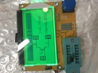
This is the best money you can spend in DIY -
https://www.amazon.com/dp/B07WT9VVZB/ref=cm_sw_em_r_mt_dp_8B9BAJ3XYMMH3H12Y2S0
Tests essentially anything/everything.
https://www.amazon.com/dp/B07WT9VVZB/ref=cm_sw_em_r_mt_dp_8B9BAJ3XYMMH3H12Y2S0
Tests essentially anything/everything.
Wow. Mind blown. This item needs to be a sticky. Just ordered one, silly this exists and I didn’t know!
Thank you thank you
Ordered another pair from the store cause I can’t get away keeping the apartment as such a electronics war room much longer
Thank you thank you
Ordered another pair from the store cause I can’t get away keeping the apartment as such a electronics war room much longer
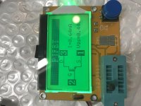
eBay sells the Mega328 tester too. Be sure to buy one that comes with the (optional!) acrylic case, or you'll wind up with a bare board ... which works fine but is a little fragile for a test instrument.
I don't think you can draw that conclusion. It may just mean one jfet "turns-off"
slightly earlier than the other.
Have you tried doing Idss measurements, as outlined here? :
JFET matching information – diyAudio Store
slightly earlier than the other.
Have you tried doing Idss measurements, as outlined here? :
JFET matching information – diyAudio Store
Last edited:
I have the same cheap tester, its very handy, but I find Idss value it provides is much lower than real value I obtain from test rig
Both jfets are ok
Both jfets are ok
Thanks for the feedback and ideas - back to the drawing board - what other culprits to investigate? Q2 is the correct piece but haven’t desoldered to test
Have spares on the way
Have spares on the way
Yup yup, they are good for identifyingI have the same cheap tester, its very handy, but I find Idss value it provides is much lower than real value I obtain from test rig
Both jfets are ok
- device type
- pin outs
- device status, i.e. shorted or open, I put a broken irf510 in, and it was shown as a diode.
However, it is a good last check before soldering the devices to the board.
LOL, it helps my aging eyes big time but won't eliminate my stupid mistakes completely 🙂
Yup yup, they are good for identifying
hfe and idss measurements are too far off.
- device type
- pin outs
- device status, i.e. shorted or open, I put a broken irf510 in, and it was shown as a diode.
However, it is a good last check before soldering the devices to the board.
LOL, it helps my aging eyes big time but won't eliminate my stupid mistakes completely 🙂
Alright, so those babies are going back in later, and then the Q2 MPSA92 is coming out to get checked.
Earlier I Noticed that when trimmer R7 (1K) is checked from the test points on either side, I am getting 1K ohm while soldered in place. Which shouldnt be th case, would this indicate an issue elsewhere or instead that the pot is malfunctioning = I removed and it seemed to test properly, but still.
- Home
- Amplifiers
- Pass Labs
- Aleph J illustrated build guide