Hey folks, posted this on another discussion regarding C1, but maybe I can get some eyes here.
Just powered up the full amp after testing PSU overnight - seem to be having an issue thats showing itself as a smoky CL60 tied into ground block.
1, PSU tested "perfectly"
2. Mods are - C1 Bridged and C6 & 7 omitted - shouldnt relate, but worth mentioning
3. Q3, and R13, 14 omitted as well.
Checking everything over and over, and I can't find any particular culprits at the moment - the ony clarification:
Channel 1 - I have solid connections from V+, V- and GND. and ALL THREE show continuity when tested against star ground or base plate.
Channel 2 - I have the same behavior EXCEPT V+ does not chime conitnuity to star ground/Baseplate
on the PSU Board, I get continuity from V+ to GND to V- as well, but seems normal.
Any targeted thoughts for troubleshooting? Should I take this to another thread? finally, Could this be that the CL60 is poorly rated for the mods and start-up current needs?
**** QUICK EDIT*** - After retesting the PSU board, it seems that the solder grounds on the connection block are weak - while I get my ~+/- 25V when going to the ground leading to star, I am not getting a nice ground when going to other two - going to reflow these after it's drained out, and see how we do. Those are all reading the same now -
Again, inrush seems fine and the issue is showing up on the CL60 inline with PSU GND to Chassis GND and earth
Thanks in advance
The CL60 from the PSU to chassis is getting hot? If yes, do not power up again.
Photos please, well-lit, in-focus, you know the drill... 🙂 🙂 🙂
Photos please, well-lit, in-focus, you know the drill... 🙂 🙂 🙂
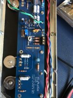
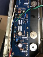
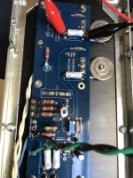
Alright, here we go....
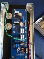
FWIW both boards are behaving identically, I just spent a nice amount of time checking on this - so it would seem that way, at least without voltage applied.
FWIW both boards are behaving identically, I just spent a nice amount of time checking on this - so it would seem that way, at least without voltage applied.
Attachments
Is it really that simple?! Wow. Easy enough I suppose!
So that I can better understand, whats happening thats causing this in this scenario
So that I can better understand, whats happening thats causing this in this scenario
I don't know yet. But I have no idea why it (C1) is not there, as all the DC issues happen on the V- side of the diff pair.
Also, why is the limiter removed? That may be adding to your woes...
Build a Lightbulb tester, that will save expensive parts moving forward.
Also, why is the limiter removed? That may be adding to your woes...
Build a Lightbulb tester, that will save expensive parts moving forward.
So it seems like one should build ones Aleph J with c1,6-7 installed, get it working, then bridge c1 and take out c6-7 if your going to, is that correct?
Hi,
I need to replace a trimmer potentiometer on one of the boards. The board has been working OK (apart from 0.3 volts DC on the speaker output, which is why I need to change the trimmer) and sounds otherwise good.
How best would I change this?
Could I just unscrew the 4 soldered transistors from the heatsinks and unscrew the board and replace the trimmer with the attached transistors? being careful not to bend the transistors.
Or would it be best to unsolder the power transistors, leaving them attached to the heatsinks?
I would not desolder the transistors. I would remove the board with the transistors and do the repair.
I would reflow the transistor joints after I put everything back together if needed.
I would reflow the transistor joints after I put everything back together if needed.
So it seems like one should build ones Aleph J with c1,6-7 installed, get it working, then bridge c1 and take out c6-7 if your going to, is that correct?
Indigent Audio,
So the general recommendation prior to doing any modifications is to build it in its stock format:
Install C1, Q3, R13 and R14.
C5, C6 are definitely optional, as are R28, R29, LED Green and LED Red, especially if you don't want/need a visual indicator that the board is "working."
C5, C6 are just bypass capacitors to C2, C3 which are large electrolytics. C2 and C3 are absolutely required.
You can add C5, C6 with your custom flavor of capacitor after you get the unit biased and working.
Hope that helps,
Anand.
- Home
- Amplifiers
- Pass Labs
- Aleph J illustrated build guide