Unless using the AN4218 will cause you to stay awake at night, I would suggest
just going ahead with it.
just going ahead with it.
The Edcor signal transformer does tend to pick up magnetic and electrostatic hum. If you don't have the AS series transformer from Antek, then I would definitely recommend getting a steel case for the one you have. And try a copper band around the Edcor as well.
- What other parts do I need that aren't listed above? I don't have a parts-bin stash like some of ya'll.
Just in case you're in the same situation, I'm waiting for some little tie-wraps to arrive. Two little bits of nylon worth next to nothing, but the simplest way to thermally couple Q1a and Q1b. (I'm sure the other 98 will come in handy, sometime.) Just a little frustrating when you have all the other bits and pieces and are itching to finish and test a new amp.
(Best to wrap the two together before soldering - otherwise you may stress or even break one or more legs.)
You mention having built a valve amp in the past, so have dealt with high voltages. All the same it's quite possible to follow a comprehensive set of instructions and succeed with no theory at all. In your place I would research power supplies and fully understand the theory and the potential dangers, and build the light bulb tester, before starting this project. (I survived my one and only brush with mains voltage while still at school, but once was enough.)
And more elegant, too which is always a bonus.
(Although applying heat to a semiconductor always goes against the grain - I don't even like soldering them to the board.)
(Although applying heat to a semiconductor always goes against the grain - I don't even like soldering them to the board.)
I've found the shrink to be very sensitive—and one of those mini heat guns—blowing hot air—does the trick and really doesn't get that hot—and it's fast, seconds. No killed Jfets yet. (Have red in the F5. Haha.)
So, I know the conventional wisdom is to build the J with the on/off switch in the back. It there a good reason it can't be on the front panel?
I am going to be building one of these as soon as I get all the bits together.
I am going to be building one of these as soon as I get all the bits together.
Nope. Do it however you please (assuming proper parts and wiring are chosen and taking wire routing into consideration). Mark Johnson has even provided a very nifty project you may consider. I haven't tried it yet, but those I know that have really appreciate the design.
PCB: low voltage On-Off switch drives AC mains relay \ includes soft start .. H9KPXG
PCB: low voltage On-Off switch drives AC mains relay \ includes soft start .. H9KPXG
Thanks for the reply.
This does look like a nice solution.
However, I found a cabinet already with the on/off switch installed in the front panel.
I figured it didn't matter and people were putting them in the back due to the fact that the 4U and 5U cases have holes in the back for the switch.
This does look like a nice solution.
However, I found a cabinet already with the on/off switch installed in the front panel.
I figured it didn't matter and people were putting them in the back due to the fact that the 4U and 5U cases have holes in the back for the switch.
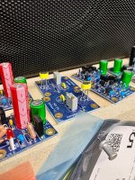
Added 4 Nichicon KG series caps into the previously empty mounts on my power board. Amp is again stable with bias and offset after 2 hours of setup burn in. Had a quick listening session to make sure things sounded good. I'll get more time to listen tonight and give my impressions with my upgrade/modification.
Attachments
I am building the Aleph J with a couple of friends across the country. We’re using Zoom to video conference and go through preparations. I looked at the Panasonic 0.47R 3W ERX resistors and noticed they have a stripe on one end of the body. Is there any significance to this stripe? I’ve never known resistors to have any polarity or directionality. I looked in the data sheet and nothing stood out to me about that marking.

It means nothing.
Style points are awarded if all your leads are bent in a way where the value is visible.
Style points are awarded if all your leads are bent in a way where the value is visible.
I have completed the power supply board and the two amp boards. I am placing an order for a black 4U Deluxe Aluminum chassis with handles. I’ve got everything else to finish it once the chassis comes in.


This build guide has been extremely helpful. Thanks again to 6L6 and all for sharing your knowledge and experience.
This build guide has been extremely helpful. Thanks again to 6L6 and all for sharing your knowledge and experience.
Looks beautiful! 😀
Remove the output snubber. Not needed nor helpful for a Class-A amp.
Are the grounds tied together on the bottom? Just checking...
Are you stacking another PSU board on top of this one? Curious about the blade connectors installed around the periphery.
Remove the output snubber. Not needed nor helpful for a Class-A amp.
Are the grounds tied together on the bottom? Just checking...
Are you stacking another PSU board on top of this one? Curious about the blade connectors installed around the periphery.
Looks Great! If you missed the suggestion in the previous posts you can place a fixed 1K ohm resistor in the R8 location, or just set that pot to 1K ohm.
Thanks all for the input/feedback.
I will remove the PSU output snubber. The jumpers between the power supply grounds are underneath. I just thought I’d have lugs in case it makes sense to to use the lugs rather than the terminal blocks. I might go with a dual mono configuration in the future.
As for the LTP Bias pots, I set both pots to 1.000 kohms.
- Home
- Amplifiers
- Pass Labs
- Aleph J illustrated build guide