You can never have too many blue LEDs!
Those blue LED are an inspiration from Jim as its a NP amp 😉
Bias problem
One problem with one channel on my Alepj J build. The other channel worked perfect.
I can regulate the bias up to 310mV on the source resitance. Offset is very low. trying to adjust offset does not affect the bias. PCB is the last edition from diyAudio. R27- is a multitrim 100 kohm. R27A is a bare jumper.
Eivind S
Congratulations on getting your J completed. As a first step I woud carefully check all the parts to make sure they are the correct value and in the proper spots on the pcb. Also check your power supply input/output wiring for that channel. Also inspect the soldering. It's easy to forget to solder something. The jumper and resistors around R27 can easily get put in the wrong spots. Follow the build guide as you check all the parts. Given that you have low offset and 310mv bias, have you tried the amp with music or test signals to see if the gain is normal and it is reproducing music? If that checks out then you have an issue with not enough adjustment range to get to .4v bias or maybe something is out of tolerance. If you are not getting amplification or are getting distorted output you should check the Jfets and other transistors. Comparing voltage readings to the good channel will give you some clues to where the issue may be.One problem with one channel on my Alepj J build. The other channel worked perfect.
I can regulate the bias up to 310mV on the source resitance. Offset is very low. trying to adjust offset does not affect the bias. PCB is the last edition from diyAudio. R27- is a multitrim 100 kohm. R27A is a bare jumper.
Eivind S
Having one good channel enables you to take voltage readings at the same points and compare. Ohm readings a the same points will also tell you something. Many repairs can be done with only a multimeter.
One problem with one channel on my Alepj J build. The other channel worked perfect.
I can regulate the bias up to 310mV on the source resitance. Offset is very low. trying to adjust offset does not affect the bias. PCB is the last edition from diyAudio. R27- is a multitrim 100 kohm. R27A is a bare jumper.
Eivind S
clarify arrangement of R8 , same for R7
referring to original sch :
Last edited by a moderator:
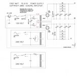
Ive attached a schematic of my proposed wiring for the PSU.
Attachment is the original posted in this thread, in the bottom third is the wiring I think is correct for a 240v single primary 2 secondary transformer. Ive looked through lots of threads but cant find a definitive answer to this exact arrangement.
So can I have peoples opinions on this proposed wiring? Thanks
Attachments
Rapid question: I'm about to finish a set of Aleph J clone PCBs and I was wondering if thermal coupling between Q1a and Q1b (J74s) is important?
Thanks,
Nic
Thanks,
Nic
R7= 2kohm multiturn and R8= 1 kohm.
Eivind S
what's voltage across R8 ?
move R27B in R27A position , leave R27B position unpopulated , set R27 trimpot to zero for start
same applies for both channels
problem with that schematic and pcb is that there was too much tips and inputs and boyz were somewhat too ambitious making both schm and pcb
so , easy to get greenhorns confused
(I know , I'm confusing my self every day ..........
 )
)Zen Mod
Can you please clear up up for me: R27- in schema I am sure is the 100k trimmer. The R27 on the PCB: Is this named R27A or R27B in schema?
Eivind S
Can you please clear up up for me: R27- in schema I am sure is the 100k trimmer. The R27 on the PCB: Is this named R27A or R27B in schema?
Eivind S
what I wrote is referring to schematic I (re)posted in #1945
I think it's clear what I meant , hopefully names on pcb corelative to names on sch
point is having 100K trimpot and 68K fixed resistor in series , not in bloody unnecessary parallel
I think it's clear what I meant , hopefully names on pcb corelative to names on sch
point is having 100K trimpot and 68K fixed resistor in series , not in bloody unnecessary parallel
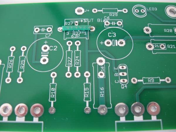
I don't have a good photo of the blue PCB, which has some minor changes to the silkscreen, but the physical layout is identical.
Please read -
In this photo you can see the (3) locations that can be called R27.
The first is the vertical resistor pad in between the capacitor pads and next to R24. Jumper this.
The second is the resistor pad across the pot pad, which in this photo has the green jumper. Leave this open.
The third is the potentiometer pad, which in this photo is hiding under the green jumper. Populate this with a 100K pot and set it to 68K to start.
Actually all that's needed is the 100K pot.
Yes. Ultimately that's my fault. But working around it is pretty simple, and the PCB has had hundreds of successful amps built... But if we ever make a Rev.2, some of the pads will be eliminated.
Please read -
In this photo you can see the (3) locations that can be called R27.
The first is the vertical resistor pad in between the capacitor pads and next to R24. Jumper this.
The second is the resistor pad across the pot pad, which in this photo has the green jumper. Leave this open.
The third is the potentiometer pad, which in this photo is hiding under the green jumper. Populate this with a 100K pot and set it to 68K to start.
point is having 100K trimpot and 68K fixed resistor in series , not in bloody unnecessary parallel
Actually all that's needed is the 100K pot.
Zen Mod said:problem with that schematic and pcb is that there was too much tips and inputs and boyz were somewhat too ambitious making both schm and pcb
Yes. Ultimately that's my fault. But working around it is pretty simple, and the PCB has had hundreds of successful amps built... But if we ever make a Rev.2, some of the pads will be eliminated.
Last edited:
well , nothing wrong with extra options , I'm just witness that boyz are often confused
though , who's urging them to tackle with nuclear bomb , as first DIY project
though , who's urging them to tackle with nuclear bomb , as first DIY project
Hello All,
I'm still in the process of acquiring all the parts for my Aleph J build project, and just recently received my order of the 4U back panel kit. In the mean time I've been watching the build thread and reading and re-reading the build guide when I came across the wiring pic of the power switch/fuse holder unit. In the build pic the jumper wires show that the line and neutral are wired to fuse both leads (the fuse block has a space for a line & neutral fuse). This would require a fuse for the neutral wire as well, when normally it would only be fused on the line side. Am I missing something in the build notes? If it is to be wired this way what value of fuse is installed on the neutral wire?

I hope I've attached the pic from the build properly.
I'm still in the process of acquiring all the parts for my Aleph J build project, and just recently received my order of the 4U back panel kit. In the mean time I've been watching the build thread and reading and re-reading the build guide when I came across the wiring pic of the power switch/fuse holder unit. In the build pic the jumper wires show that the line and neutral are wired to fuse both leads (the fuse block has a space for a line & neutral fuse). This would require a fuse for the neutral wire as well, when normally it would only be fused on the line side. Am I missing something in the build notes? If it is to be wired this way what value of fuse is installed on the neutral wire?
I hope I've attached the pic from the build properly.
Yes, wire it as shown. Those connections attach the IEC portion to the switch.
The fuse holder is integral to the IEC plug, so you can't defeat the fuse by sipping the switch on the neutral.
Jumper the neutral fuse if you want or make the fuse value double, to essentially make it a wire.
MAKE SURE you have only the hot fused if you use a single fuse.
The fuse holder is integral to the IEC plug, so you can't defeat the fuse by sipping the switch on the neutral.
Jumper the neutral fuse if you want or make the fuse value double, to essentially make it a wire.
MAKE SURE you have only the hot fused if you use a single fuse.
Thanks for your quick reply 6L6! So seeing as the Aleph J manual asks for a 4amp slow blow fuse, then I'd put one each in the line and neutral positions of the holder? Just want to be clear on what you've suggested.
Thanks Again!
Thanks Again!
Or did you mean to double the fuse value of the neutral? Lol, just thought about that after posting.
- Home
- Amplifiers
- Pass Labs
- Aleph J illustrated build guide