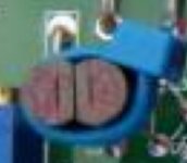
To-92 package have the same cbe polarisation
look at flat side of plastic like on picture 🙂
Thanks, good call. The numbers are so small and close to each other that it is easy to put the wrong transistor in place.
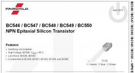
I used the Fairchild Semiconductors...not the Zetex.
I used the Fairchild Semiconductors...not the Zetex.
Cool Whaleman 🙂
All TO-92 packages have the same collector-base-emiter polarisation
they are all standard despite the brand used.
The numbers are so small and close to each other that it is easy to put the wrong transistor in place.
Truth!
Some times i zoom at maximum with smart phone to see the code.
Nice trick is thermal coupling of jfets Q1A and Q1B on pcb
like show on 6L6 photo.
Some diyers put little drop of thermal grease in between
for perfect themperature match.
Hope i make play my Aleph too 😀


Attachments
Last edited:
All TO-92 packages have the same collector-base-emiter polarisation they are all standard despite the brand used.
In a perfect, harmonious world, that would be true.
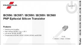
But it is not true - always check the datasheet. In fact, there are sometimes different pinout available in the same transistor.
On the Aleph J circuit board, there is a reason why the bipolar transistor silkscreen is not shown with a flat side, and instead is genderless with collector base emitter labeled - the BC transistors (easy to get in Europe) are CBE, but the ZTX (easy to get in N.America) are EBC.
Check the datasheet, check the stuffing diagram.
Always.
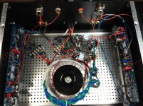
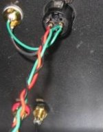
Spent 3 hours to arrive at the same exact place, with faint hum in the right channel. You can see in the pics how the wire and shield look.
Me thinks I need to remove the board a second time and measure every single resistor, even if I have to lift one end up.
Already checked every solder connection when I had it out.
Hi Whaleman
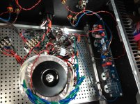
Your amp looks great. Hum problems can be frustrating. One thing that comes to mind is that your filter caps are very close to the front end. There are large currents flowing through the wires from the bridge and through the capacitors. This could be the cause of your problem. The transformer is centred so I would think any hum would be equal in both channels. You could try temporarily moving the cap bank further away from the board to see if that helps.
Brian
Three more hours wasted:
No a single change.
OK, here is the biggest clue!
If I take a wire connected to the chassis and touch the signal negative at the RCA:
L: Good channel, hum appear from dead quiet sounds like a group loop problem
R: Bad channel, faint hum becomes noticeable, and sounds just like a tube radio with bad power caps
So behavior of hum is different from one channel to the other, one is like ground loop, one is like bad power cap filtering.
Pictures.
- Remove toroidal, move around case, has no effect on hum
- Check Q2, Q3, Q4 orientation, swap in a couple spares
- Move power caps closer to center
- Check every single resistor and capacitor
- Check and recheck solder top and bottom
- Reroute input wires away from everything
No a single change.
OK, here is the biggest clue!
If I take a wire connected to the chassis and touch the signal negative at the RCA:
L: Good channel, hum appear from dead quiet sounds like a group loop problem
R: Bad channel, faint hum becomes noticeable, and sounds just like a tube radio with bad power caps
So behavior of hum is different from one channel to the other, one is like ground loop, one is like bad power cap filtering.
Pictures.
Attachments

Last edited:
use shielded for inputs
connect fat wire bridge between two channel pcbs main gnd point
route power rails in shortest path from cap bank to channel pcbs
connect fat wire bridge between two channel pcbs main gnd point
route power rails in shortest path from cap bank to channel pcbs
Hi Whaleman and 6L6
Thanks for yours answer 🙂
I learn every day that is great side of diy.
Question for Whaleman :
Do you have jumper in yours XLR inputs, wiring all is ok ?
Best regards
Thanks for yours answer 🙂
I learn every day that is great side of diy.
Question for Whaleman :
Do you have jumper in yours XLR inputs, wiring all is ok ?
Best regards
Attachments
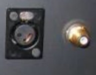
Yes, I have a jumper from chassis to ground on the XLR, both channels are wired the same.Hi Whaleman and 6L6
Thanks for yours answer 🙂
I learn every day that is great side of diy.
Question for Whaleman :
Do you have jumper in yours XLR inputs, wiring all is ok ?
Best regards
OK, here another clue:
Short input +/- at RCA jack:
L: silence
R: very noticeable power type hum
The type of hum is not stray pickup, or ground loop. Many of the solutions you are suggesting are to correct these types of hum.
Attachments
L: silence
R: very noticeable power type hum
do you have a split power supply? if so, measure the ripple at left and right ps capacitors. A faulty electrolytic could be the culprit
do you have a split power supply? if so, measure the ripple at left and right ps capacitors. A faulty electrolytic could be the culprit
The bipolar power supply is shared equally by both channels, there are three electrolytics at each channel, 220uF, 220uF, 10uF, all Elna Silmic and measure to spec. But there is that possibility...
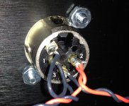
XLR from 6L6 guide have 3 wires in : green, black and red
and they 2 out go in to
rca : black and green

Anodised painting is not isolation from the box ?
Your 1,2,3 XLR red , green is not the same wiring position.
Greetings
and they 2 out go in to
rca : black and green
Anodised painting is not isolation from the box ?
Your 1,2,3 XLR red , green is not the same wiring position.
Greetings
Last edited:
did you tried what I wrote ?
at least that fat bridge
Going to as soon as I get back to the unit, thanks.
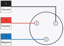
This is the wiring for the XLR I followed:
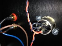
I have another thought, one of the standoffs is bleeding chassis ground to a trace on the PCB.
Attachments
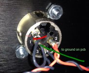
yup
pin1 on audio gnd , not case
when pin1 is going to case , you need different approach for audio gnd/case relation
pin1 on audio gnd , not case
when pin1 is going to case , you need different approach for audio gnd/case relation
Try input ground to go directly into input gnd section on pcb ?
yup
pin1 on audio gnd , not case
when pin1 is going to case , you need different approach for audio gnd/case relation
Cool, now I got something to try!

I had time to try everything you guys suggested, nothing worked. Once again, this is not stray pickup noise, or a ground loop or open ground problem. I proceeded after that to replace all capacitors, the zener diode, Q2, Q3, Q4, check all resistors.
The only time the hum went away was when I removed Q1A and Q1B. Unfortunately, I did not follow advise and got them off the eBay place.
I will have to do that again unless one of you comes up with a pair of Linear Systems J74S or four Toshibas J74S that they want to sell me. PM if so or point me to a member that might have some to go.
The amp will sit on the shelf until that happens...🙁
Nevertheless, thanks for all the help, we will get it right eventually.
- Home
- Amplifiers
- Pass Labs
- Aleph J illustrated build guide