DIY is catching, thats for sure. I am yet to solder the first part of my Aleph J, and have a working pre-amplifier.
I will be investigating the balanced Zen when I get the itch to build something once my Aleph J is working smoothly.
I will be investigating the balanced Zen when I get the itch to build something once my Aleph J is working smoothly.
The MOSFET case temps stabilize in the upper 60s in a 25deg room at the 400mV bias described in 6L6's guide. 500mV is in the low to mid 70s.
There is no question that the 4U is about the absolute minimum for heatsink size. The chassis itself is the perfect size. 🙂
My home made chassis will be 4U in height (165mm), 485mm width, 400mm in depth. But then my heatsinks will be much more efficient than those that comes with the Store chassis. 76mm with 60mm fins. For me that will be absolute minimum also because our ambient temperature can shoot up to 43 degrees C in summer.
OFF Topic
😱 Hi.
Sry... for this offtopic quistion.
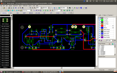
I am about to make a Aleph-J (DIY from scratch). The mounting of the Q5 , 6, 7 and 8, will be wired (10cm approx.) from the PCB.
So my quistion is : Is it wise to "hardwire" or eventually small outputboard the R9, 10, 11 and 12 and the R16, 17, 18 and 19 so those parts will be close to the mosfets ?
// Jesper.
- Attach. screenshoot of proto -layout...
😱 Hi.
Sry... for this offtopic quistion.
I am about to make a Aleph-J (DIY from scratch). The mounting of the Q5 , 6, 7 and 8, will be wired (10cm approx.) from the PCB.
So my quistion is : Is it wise to "hardwire" or eventually small outputboard the R9, 10, 11 and 12 and the R16, 17, 18 and 19 so those parts will be close to the mosfets ?
// Jesper.
- Attach. screenshoot of proto -layout...
Attachments
only gate resistor is wise to have ditto on mosfet , even if not so critical , when 10cm is in question
Great....
I will try to convert my layout to this, with the usually Nelson 221R resistors 😎
/ Jesper
I will try to convert my layout to this, with the usually Nelson 221R resistors 😎
/ Jesper
6L6
I follow your text regarding R27. You just jumper-ed the Pot at R27 and stuffed a resistor. What was the resistor? Did you not think it was necessary to tweak the POT and swap out resistor?
I follow your text regarding R27. You just jumper-ed the Pot at R27 and stuffed a resistor. What was the resistor? Did you not think it was necessary to tweak the POT and swap out resistor?
balanced zen linestage as a preamp, I assume this has gain whereas the B1 is only a buffer. Would this be a good compliment to a F5 as well as Aleph J. If someone creates a pcb I would be interested also in joining a group buy.
Does the absolute value of IDSS matter for the j74 k170 pair as long as the values match? Does grade itself matter A b c d. I noticed the A's went first for the linear device j74 and k170's. Why?
A related question: How close is "matched"? .1? .2 ? .5. ?
I am not an engineer 🙁
A related question: How close is "matched"? .1? .2 ? .5. ?
I am not an engineer 🙁
IRF - Matching!
Hi again...
collecting parts, and making pcb's, i was wondering about some things ::
How close must i match them IRF's ? (VGS only ???)
Q5 / Q6 (CCS) and Q7 / Q8 does they have to be quad matched ?
>> Thanks...
/ Jesper
Hi again...
collecting parts, and making pcb's, i was wondering about some things ::
How close must i match them IRF's ? (VGS only ???)
Q5 / Q6 (CCS) and Q7 / Q8 does they have to be quad matched ?
>> Thanks...
/ Jesper
Hi, when using recommended psu/rail for Aleph J, is the Conrad Engineering MF30-2F-151.5 or MF35-151.5 heatink enough per channel?
These are 0.25 and 0.21 C/W ratio.
Better yet, what C/W thermal rise ratio is recommended for Aleph J per channel?
These are 0.25 and 0.21 C/W ratio.
Better yet, what C/W thermal rise ratio is recommended for Aleph J per channel?
IIRC, Conrad have their numbers for a 80C ambient, the more relevant C/W numbers are higher at lower ambient. I could be way off base here since I'm far from expert or possibly not competent :'(
Smiley not working :-(
Smiley not working :-(
Last edited:
(first) You just jumper-ed the Pot at R27 and stuffed a resistor. What was the resistor? Did you not think it was necessary to tweak the POT and swap out resistor?
The original value resistor was 68.0K I changes it because my amp was not working properly (intermittently weird) and thought having control of that value via the pot would help. The issue was a bad solder joint.
The pot remained in place so I could adjust the bias and make measurements, etc...
Does the absolute value of IDSS matter for the j74 k170 pair as long as the values match?
Within the range of 7.0-10.0 (or maybe wider...) not really. The match of the differential pair (the 2 jfets) is more important.
Does grade itself matter A b c d. I noticed the A's went first for the linear device j74 and k170's. Why?
Who knows. The A are lowest range of Idss. The letters are not quality, only operating range. The B would be the best for the Pass projects, but all can be made to work.
A related question: How close is "matched"? .1? .2 ? .5. ?
.1 is fine, .2 in a pinch.
Q5 / Q6 (CCS) and Q7 / Q8 does they have to be quad matched ?
No. The CCS fets and the output fets need to be matched -- 2 pairs per channel. If you can quad match it certainly won't hurt.
Quote:
Originally Posted by lykkedk
Q5 / Q6 (CCS) and Q7 / Q8 does they have to be quad matched ?
No. The CCS fets and the output fets need to be matched -- 2 pairs per channel. If you can quad match it certainly won't hurt.
Thanks 6L6 - you are very kind...
Keep up the good work there 🙂
Btw:: i am in slow start making a Aleph J, from scratch... E.g. I make the pcb's myself, chassis and whatever.
Is it best, i make a new post, or can i continue posting my build (slow) here ???
- what do you prefer ?
// Jesper
- Home
- Amplifiers
- Pass Labs
- Aleph J illustrated build guide